A ring on the primary conductor, and the whole driver's view of what the coil is doing. Take both jobs off one of them and the protection goes soft exactly when you need it.
What it is and why
The conductor itself is the one-turn primary; the winding on the ring is N turns of secondary. The current in that winding is N times smaller, and a burden resistor turns it into a voltage the driver can read.
I_secondary = I_primary / N, U = I_secondary × R_burdenThat is the whole device. Two of them appear on a DRSSTC because the driver wants two different things from the primary current: the phase of it, to know when to switch, and the size of it, to know when to stop.
What you decide
Two rings, or one
Criterion: whether anything is loading the transformer that also has to carry the protection.
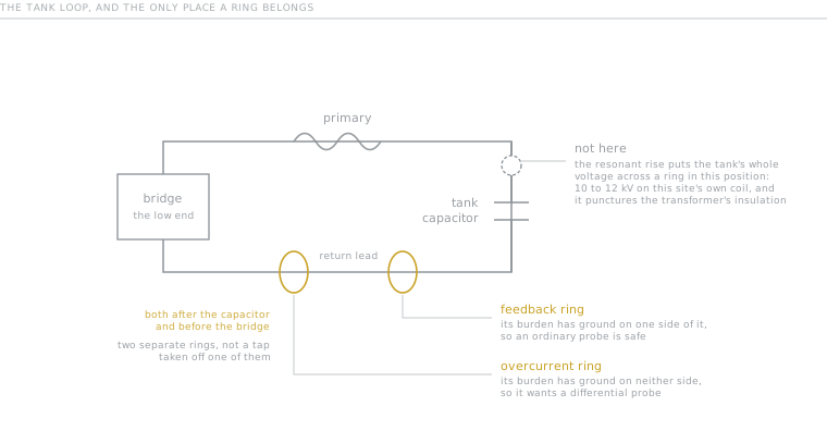
The picture is the argument in one line: two rings on the same lead, and both of them at the low potential end of it. Everything below is why each half of that sentence matters.
The feedback path has a phase lead network hanging off it, and that network loads the first stage. The core saturates, and the protection gets weaker exactly when it is needed. The UD2.x boards keep the two apart, and that is not an accident.
How many turns, and whether to cascade
Criterion: the burden you want. More turns means less secondary current, which means a larger burden for the same voltage.
A QCW wants a much smaller ratio than a DRSSTC, and the reason is the ramp itself. Gao winds his QCW's feedback at 175:1 on two cascaded cores, with the phase lead tapped at 100:1, against "say 1000:1 in a conventional large DRSSTC". His reason is the start of the bang rather than the size of the machine: "at the beginning of the pulse, the bus voltage is quite low, on the order of 30 to 40V. Combined with the low primary impedance, the primary current will begin much lower than a conventional DRSSTC." A ratio chosen for hundreds of amps has nothing to read when the ramp opens, which is exactly when the loop has to find the pole. That machine peaks at 100 A with 150 as its maximum, so the ratio is sized against a current that never gets near a DRSSTC's.
When one core cannot carry the turns, two go in cascade and the ratios multiply. Mads Barnkob's DRSSTC II is the arrangement written out: "two cores with 33 windings on each and one winding going through the second", which is 1:33:33 and therefore 1:1089. Steve Ward's general guide to DRSSTC design does that on DRSSTC-1, with a pair of cores in the feedback path: "Both of them are a 1:33 ratio, and being cascaded, the final current reduction ratio is 1:1089 or roughly 1:1000." And he does it twice. The active current limiting on the same schematic gets "a cascaded pair of CTs (1:33 ratio on each)" of its own, which is this page's argument drawn as a circuit: not a tap off the feedback chain, a second chain. In this page's notation that is 1089:1, and it is Ward's coil rather than the board the burdens below come from, for which no ratio is published. Work yours out from the burden you want.
The burden, and the phase error it brings with it
An ideal current transformer is a current source and gives no phase shift into a pure resistor. A real one does, and it is a lead, not a delay:
phi_error ~ R_burden / (w · L_magnetising) [radians]Count it with a minus sign: when you add up the total lead, this term subtracts. At 51 Ω it is a few nanoseconds, up to four per cent of the whole lead; at 3.6 Ω it is a fraction of a nanosecond and irrelevant.
So how much less. The burden carries two errors, not one, and they pull opposite ways. The magnetising term is the one above. The second is leakage: the inductance left uncoupled between the windings sits in series with the burden, and in time it comes out as L_leak / R_burden, the same at every frequency, because the angle rises with w and dividing by w to get time takes the frequency straight back out. So the error a burden hands the loop is
t_error  =  R_burden / (w² · L_m)   +   L_leak / R_burden
            magnetising                 leakage
            worst at the lower pole     flat across the whole ramp
One term rises with the burden and the other falls, so what the burden has is a minimum, not a direction, and it sits where the two are equal:
R_best   =  w_lower · sqrt(L_m · L_leak)
t_floor  =  2 · sqrt(L_leak / L_m) / w_lower
sqrt(L_leak/L_m) is sqrt(1 - k²), the winding's coupling defect, so that floor is set by how evenly the turns are laid and by nothing else. No burden gets under it. If you want less error than the floor, the answer is a better wound ring, not a smaller resistor.
Both inputs are measurements, and they are the two the bench sheet already asks for: inductance at the secondary with the primary open is L_m, with the primary shorted it is L_leak. A neatly wound 20-turn ring gives 920 µH and about 0.18 µH [derived, from N²·A_L on PC40 and from k ~ 0.9999], which puts the best burden at 26 Ω at the 317 kHz lower pole, and the floor at 14.2 ns, or 5.3 % of a 270 ns lead. Run over the values people fit:
 3.6 Ω    51.9 ns    19.2 % of the lead
10 Ω      21.1        7.8
26 Ω      14.2        5.3   <- the minimum
47 Ω      16.8        6.2
51 Ω 17.6 6.5Three things fall out that a single recommended value hides. A sloppier winding wants a bigger burden, not a smaller one, because R_best goes as sqrt(L_leak): at the bench sheet's 0.5 µH pass mark the best value is 43 Ω, and at its 2 µH the best value is 85 Ω [derived, both]. The 47 to 51 Ω on Gao's coil and on this one is not tradition, or not only tradition, since a well wound ring at DRSSTC frequencies puts the minimum at 40 to 42 Ω and the curve through there is flat enough that the difference is not worth an argument. What makes those values wrong on a QCW is not the number but the sweep: the minimum follows w_lower, so it moves from 42 Ω at the top of this trajectory to 26 Ω at the bottom. Size at the bottom, where the magnetising term is largest and the lead is scarcest.
The lead coil's own DCR sits in series with the burden and belongs in the formula: phi = arctan(wL / (R_burden + DCR)).
Feedback strength, which is the number to compare
How many turns is not a meaningful figure on its own. This is:
feedback strength = |Z| / N [volts per amp of primary current]where |Z| is the whole burden network, resistor and lead coil together. From it falls out the current at which the signal hits the clamping diodes:
I_clamp = V_f · N / |Z|Working boards sit around 0.02 to 0.04 V/A, on rings that carry feedback and nothing else. A ring that also sets the current limit sits lower, for the reason in the note further up.
When the choice is not yours
Everything above assumes the ratio and the burden are yours to pick. On a bought board they may not be. Eastern Voltage Research's Universal DRSSTC Controller fixes the ratio outright and takes most of the burden out of your hands. Its feedback pads take "a 1000:1 current sense transformer", its protection pads take a second one, also 1000:1, and neither burden is a number the builder sets. The sheet never uses the word: it names the ratio, asks for nothing across the input, and leaves the burden inside the box by omission rather than by statement, which is our reading of its silence and not a line you can quote from it. Two rings, two identical ratios, and the resistive half of the burden settled before the board reaches you.
Only that half, though. The other half of the same network, the lead coil this page has been counting in |Z| all along, the board hands straight back: it arrives as socketed plug-in inductor modules, IND-1 to IND-8, and the builder picks one by the size of the switch, 9 to 15 uH at the small end and 60 to 100 uH at the large. So the ratio is fixed, the resistor is fixed, and the reactance is a choice made with a screwdriver. Anyone reading the formula above will see what follows: swapping the module moves |Z|, so it moves the feedback strength too, even though the reason you swap it is the switching instant rather than the signal. The two are the same network and cannot be tuned apart.
That is the one-amp convention cast in metal. At 1000:1 a machine pulling a thousand amps of primary current hands the board one amp, and the sheet's rated ceiling agrees: 1000 A on the standard unit, 2000 A on the other. What stays adjustable is the protection threshold, 50 A to 2000 A on two potentiometers, coarse and fine, added together. The ratio does not, and neither does the resistor behind it.
The trade is the usual one. Nothing to calculate and nothing to get wrong, against no way to move the feedback strength if your machine runs two hundred amps rather than a thousand. Boards that leave the burden to you pay for that freedom with a phase error you then have to hunt down. This one pays for the absence of the hunt by fixing where you land.
And a board from the other side of the trade lands on the same ratio. terrariaking publishes a DRSSTC driver on OSHWHub that leaves the burden to the builder and states the threshold as a formula rather than a number: "阈值电压(lm393的3脚电压)=(要设定的过载电流/互感器匝数)采样电阻阻值", the voltage at the comparator's pin 3 being the overcurrent setting divided by the transformer's turns and multiplied by the sampling resistor. The board fits 10 Ω there and notes "R5=10Ω时1V≈100A"*, one volt for about a hundred amps. Put those together and the ratio falls out: a hundred amps through N into ten ohms making one volt needs N = 1000 [derived]. A hobby board in another language, with the burden left open and no datasheet convention to follow, arrives at 1000:1 anyway. That is worth more than either page saying it alone.
And the feedback ring has a direction, which this page had not said. Get it backwards and the machine does not run at all: the sheet's phase select switch "allows the user to reverse the phase of the output gate drive with respect to the phase of the primary feedback current", and it says the switch "has the same effect as reversing the wires (or direction of the primary lead) of the feedback current transformer". Its own instruction is the one to keep whatever board you run: "if during initial testing, you find your DRSSTC system is not self-oscillating and switching, to simply power down the system and change the phasing". A coil that will not start is a coil whose feedback ring may simply be round the wrong way, and that is a two minute check rather than a fault to diagnose. Note which failure this is not: it is not a phase error to be trimmed, it is a sign reversal, and no amount of lead inductance corrects it.
One line from that sheet is worth having whichever board you run: "Be sure the wires between the current sense transformer and the controller are twisted tightly together to maximize coupling and reduce inductance." Both rings feed low-level signals across a machine that is radiating hard, and the twist is what stops the run between ring and board from becoming a third winding.
Where to put it
Where the potential is low. There is a second option, and Ward allows for it in the guide linked above: "This design uses primary current feedback as the basis, but could also work from secondary base-current feedback if so desired." His next sentence says primary feedback is what he prefers. A ring at the base of the secondary on the ground wire reads secondary current instead, and what argues against it has nothing to do with the protection, which sits on its own primary ring either way. It is the drive signal. Under a ground strike the secondary jumps to a harmonic of its own resonance, so a loop reading secondary current is reading the one part of the machine that has stopped reporting itself. That is what a ground strike does to a DRSSTC, and it is why the feedback comes off the primary at all.
Wind it the wrong way round and the feedback gives you zero or chaos. Turning the ring over is the test, and it costs nothing to try first.
What will get you
And only one of the two can be probed with an ordinary probe. The feedback burden has ground on one side of it. The overcurrent burden has ground on neither, and needs a differential probe. Note also that a signal generator delivers orders of magnitude less current than a primary does, so to test a ring on the bench, wind ten to a hundred turns through it to get a signal at all.
The numbers
- Ratio in use: 1089:1 on Ward's DRSSTC-1, two cascaded cores at 33 turns each, with a second pair of the same for the limit. No ratio is published for the board the burdens below come from.
- Burdens on a UD board: feedback 51 Ω 2 W, overcurrent 5.1 Ω 0.5 W.
- Feedback strength on working boards: 0.02 to 0.04 V/A.
- Phase error at 51 Ω: a few nanoseconds, up to four per cent of the whole lead, and it subtracts. At 3.6 Ω it is negligible.
What goes wrong
- The coil will not start, or the frequency is nonsense. Winding direction. Turn the ring over.
- The protection is weak at exactly the current that matters. One ring doing both jobs, with the lead network saturating its core.
- It tracks at low power and stops tracking at high. Clamping, from a feedback strength three or four times what it should be.
- The transformer failed with a hole in its insulation. It was between the tank capacitor and the primary, at kilovolts.
- Bench tests on a signal generator show nothing at all. Not enough current. Wind more turns through the ring.
Where next
- Inside the driver, which is what these two signals go into.
- Overcurrent is not a setting, the protection side in full.
- DRSSTC phase lead: what it is made of, which inductor to fit, the network that loads the feedback ring.
The two rings on the DRSSTC diagram are drawn separately and labelled separately for the reason at the top of this piece. On the QCW page, taking the tank capacitor out removes the overcurrent one and leaves the feedback.
- Feedback strength does the
|Z| / Nabove and tells you the primary current at which the loop takes over from the oscillator, which is the number this page argues is worth more than the turns count. - CT timing works the two terms of the phase error and finds the burden that minimises them, on your own magnetising and leakage figures rather than this page's.
- Where the feedback comes from, the three places the signal can be taken from and the failure that sorts between them.