A driver that follows the current has to get that current from somewhere, and there are three places to take it from. Which one you pick is usually inherited from whichever schematic you copied, and it decides which failure your coil is prone to.
What it is and why
The loop is the same in all three cases. Something senses what the resonator is doing, the driver squares that up and switches the bridge in step with it, and the bridge feeds the resonator, which is what the sensor is watching. Close the loop the wrong way round and it does not run at all. Close it on the wrong signal and it runs at the wrong frequency, which is worse, because it runs.
What differs is only the sensor, and there are three of them in use:
- a current transformer on the primary, which is the ring the DRSSTC world means when it says feedback;
- a current transformer on the secondary, which is older and still standard on plain SSTCs;
- an antenna, a short wire near the coil that hears the field instead of measuring a current.
All three answer the same question, which is when the resonance crosses zero. They disagree about which resonance.
Two of the three, on one board, with two different front ends
Daniel Marks' half-bridge and SSTC driver puts a Current Transformer terminal and a Feedback Antenna terminal on the same sheet, screen printed with those words, and it does not treat them the same way afterwards.
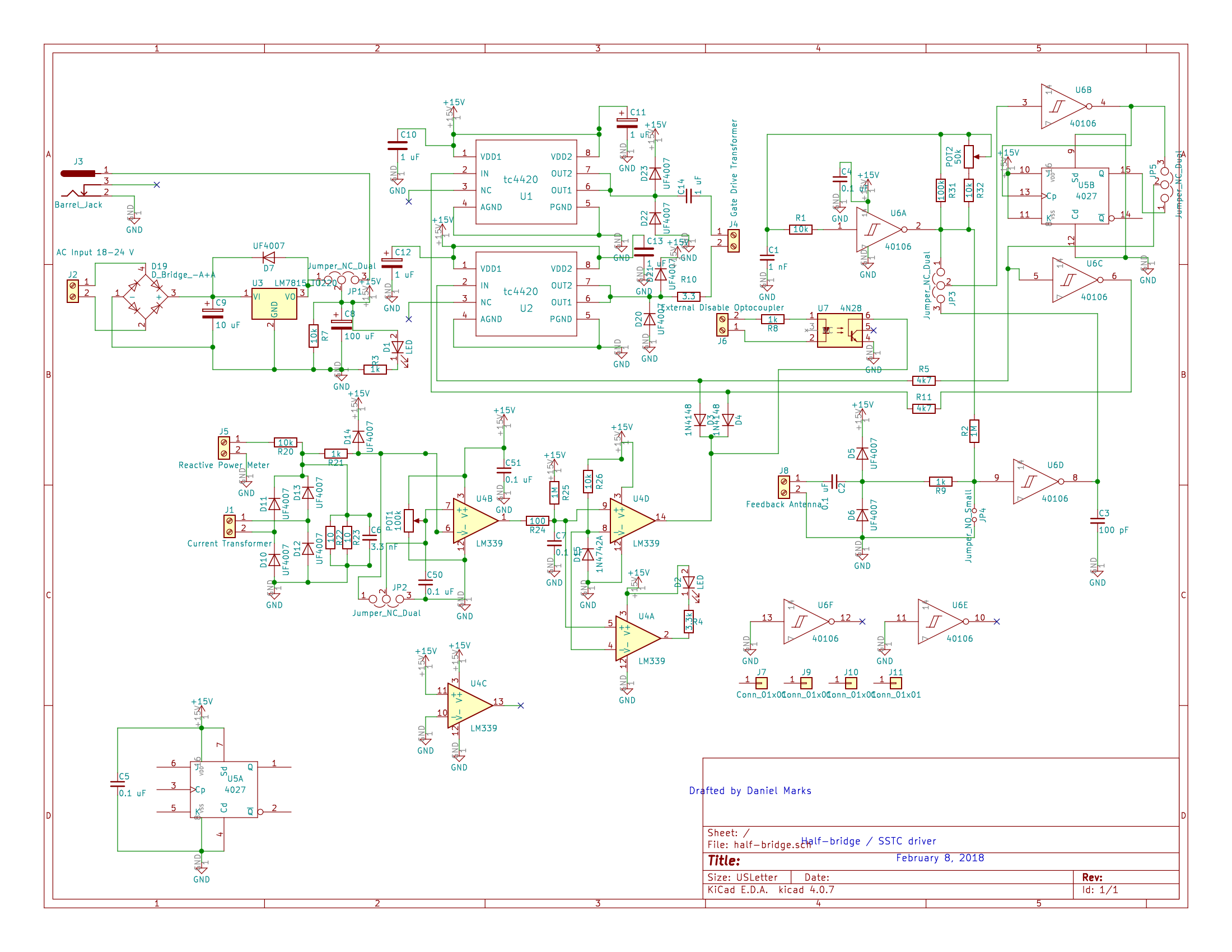
The ring gets a comparator with an adjustable threshold. The antenna gets a Schmitt trigger. The current transformer at J1 runs into an LM339 with POT1, a 100k potentiometer, on its reference. The antenna at J8 runs through a 0.1 µF capacitor and a pair of clamps into a section of 40106 and nothing else, so the threshold on that path is whatever the logic family happens to have that day.
That asymmetry is ours to read rather than the author's to explain, and the reading is this. A comparator's value is a threshold you choose and keep; it is worth its part number on a signal whose amplitude is stable and whose crossing you want to place exactly. Barnkob's complaint about antenna feedback is that "the antenna feedback can vary a lot in waveform and amplitude", and against a signal like that a chosen threshold is not buying what it usually buys, because the level it is compared against moves anyway. So the board is not being careless on one input and careful on the other. It is spending the precision where the signal can hold it. Which is also the reason the antenna path costs phase lead you did not choose: a Schmitt's hysteresis is a delay whose size depends on how fast the signal is moving through it.
What you decide
Which of the three, and it is a failure analysis rather than a preference
The primary current is the DRSSTC answer, and it is a fix rather than a choice. Under a ground strike the secondary stops ringing at its own resonance, so anything following the secondary starts switching at the wrong instants into a full bus, and the bill lands on the bridge. Taking the signal off the primary makes the loop deaf to that. The reasoning, in Steve Ward's own words and with the four other things a strike does, is what a ground strike does to a DRSSTC, and the decision itself is worked inside the driver.
And there is a second objection to the secondary that has nothing to do with strikes. ZCS is a statement about the primary. Steve Ward, working out in his log book why he kept losing IGBTs "for no good reason", sets it up that way: "DRSSTCs should normally operate in a ZCS (zero current switching) condition. That is, the current in the primary circuit is sinusoidal when the drive voltage is at resonance with the LC." Then he turns on his own sensor:
First possible flaw here is that I am using secondary current to derive my drive signals. Who says the secondary is doing the same thing as the primary current? It isn't necessarily.
That is the whole of it. The quantity you must switch at the zero of is the primary current, and a secondary current transformer is measuring something else and hoping the two agree. His conclusion, and he shares the credit for it, is "to use primary current feedback to derive the drive signals. This should in theory yield almost perfect ZCS conditions!", an idea he calls "partially inspired by Steve Conner and Terry Fritz". So the primary answer has two legs, not one: it survives a strike, and it is measuring the right quantity even when nothing is being struck.
The secondary current is what the primary answer replaced, and it is the sensor that argument is against. Whenever the arc reaches something earthed the secondary stops ringing at its own resonance, and a loop watching the secondary follows it there. It is still ordinary on a plain SSTC and it works on one, but that is because a plain SSTC hits things with less behind it, not because the mechanism is absent. Nobody in this corpus has measured what a strike does to an SSTC, so read the difference as one of degree that has not been quantified rather than as a machine that is exempt. It has a second failure of its own, below.
The antenna is a real architecture and not only a bodge, though it is both in different hands. Mads Barnkob's Kaizer SSTC 2 takes its frequency off one and finds the new frequency by itself when the winding is moved, which a free running oscillator cannot do; that comparison is with the SSTC primary. A Chinese build published as micro sstc by ampere goes further and makes the antenna the whole front end, picking the tracking signal out of the field with an antenna and a 1N60 detector diode in place of a current transformer. Coils built this way exist and run, so the question is not whether it works but what it costs.
Four things, and the last decides it. The first is from the man who runs one: Barnkob notes that "the antenna feedback can vary a lot in waveform and amplitude", which is the practitioner's version of the objection and worth more than a critic's, because a signal that varies in amplitude is a comparator threshold that means something different from one bang to the next. The second is phase lead you did not choose, which is two sections down. The third is that it is one of the two arrangements davekni names as prone to locking onto the second mode, which is the next section. And the last, ours rather than anybody's: an antenna sits on the wrong side of the argument the primary answer was built on. That answer exists to make the loop deaf to the secondary during a strike, and an antenna is the most sensitive thing you can point at a secondary. So the antenna and the secondary current transformer are not two options against one; they are one class of choice against the other, and everything said about a strike applies to both.
Which makes the recommendation a plain one. Use it where the machine is small and the arc is not going to reach anything earthed, which is what both published builds are. On anything that throws an arc into a room, put the sensor on the primary.
Which failure each one is prone to
This is the part that is worth carrying, because it is one mechanism and it sorts the three.
A coil can lock onto its second mode and run there. Not the third harmonic of the right frequency, but the wrong resonance outright, and the frequency is high enough that it kills IGBTs. davekni's account is that standard SSTCs with long secondaries and short antennas, or with secondary current feedback, sometimes fail exactly that way. What the second mode is and where it puts its voltage is its own page.
And the same account says which geometry escapes it. On a coil with a short secondary and a comparatively large topload he expects antenna feedback to avoid the instability, because the antenna hears the topload far more than it hears the middle of the winding. That is the criterion in one sentence: the antenna is listening to the end of the resonator, the second mode lives in its middle, so a coil whose end dominates is a coil the antenna hears correctly.
Whether to add one to fix a start-up problem
No, and the person who explains the mechanism says so.
A coil that starts only while a scope probe sits on the comparator input is being started by the probe: the probe and its lead are an antenna, picking up noise or, more likely, voltage from the secondary, and that pickup makes the extra transitions that begin the oscillation. RoamingD found exactly that and davekni explained it. Of his three options, adding a real antenna is the one he does not recommend, and the reason is that it gives uncontrolled phase lead. The other two are to fix the actual start-up problem or to make the driver self-oscillating, and the whole of that argument is every bang starts open loop.
What will get you
And the sensor is not the protection. Whatever you take the frequency from, the overcurrent detector wants a ring of its own and it wants it on the primary, because that is where the current the bridge cannot survive actually flows. One sensor doing both jobs is the mistake the current transformer page opens with.
The numbers
primary current CT    the DRSSTC answer, after ground strikes
secondary current CT  older, ordinary on a plain SSTC
antenna + detector    ampere's micro sstc: antenna and a 1N60 in place of a CT
There are no ratios or lengths on this page on purpose. An antenna's length and placement are not published as a rule anywhere this corpus has read, and the two builds that use one give a circuit rather than a dimension. What is established is the failure and the geometry that sorts it, and that is what is above.
What goes wrong
- The coil runs at a frequency far above the one you tuned for, and IGBTs die. The second mode, locked onto directly. Long secondary, small topload, and either a short antenna or secondary current feedback.
- The coil will not start at all. The sensor is round the wrong way. It is a sign reversal and it takes ten seconds to test.
- The coil starts on the bench and not in the room, or only with a probe attached. The probe is the antenna. Fix the start-up rather than keeping the probe.
- Switching instants go wrong when the arc hits something earthed and the bridge pays. Feedback that can hear the secondary, which is the secondary current transformer and the antenna alike. This is the failure the primary current answer exists for, and the reason not to reach for either of the other two on a machine whose arc leaves the topload.
- The protection is weak exactly when the current is highest. One sensor asked to do feedback and protection at once.
Where next
- Inside the driver, where the primary current answer is worked with the numbers.
- What a ground strike does to a DRSSTC, the failure that produced that answer.
- The second mode, the failure that sorts the other two.
- Every bang starts open loop, because none of the three has anything to follow until there is something to follow.
The current transformers on the department diagram are drawn on the primary side, which is the DRSSTC answer. A plain SSTC often has neither of them there, and the sensor is somewhere the diagram does not draw.