A current feedback loop cannot start itself. The signal it runs on is the thing it is there to produce, and at the instant the interrupter says go, that signal is zero. So the first cycles of every bang are commanded by something that is not measuring the coil, and the moment measurement takes over is a mechanism in its own right, with its own settings and its own ways of failing. Three published drivers build that moment three different ways. What it looks like when it goes wrong is a coil that will not start, or starts on some bangs and not others, and that is also what a loop with too little gain looks like, so the first thing worth knowing is which of the two you are holding.
What it is and how it works
An oscillator made of an amplifier and a sensor is a loop with a sign on it. The amplifier drives a load, the sensor watches what the load does, and the sensor's output decides when the amplifier switches next. Nothing in the circuit sets the frequency. The load sets it and the circuit follows. That is the whole appeal of the arrangement, and it is why it is reached for wherever the load's frequency is not known in advance or will not stay still.
Now read that description again and notice that nothing in it starts. The sensor watches the output. Before the amplifier has driven anything there is no output to watch, so the sensor says nothing, so the amplifier is never told to switch. The loop is complete, correct, and asleep.
There are three ways out of that. Let noise grow: with enough gain round the loop and enough Q in the load, whatever is on the input gets amplified round and round until it dominates. Drive the thing deliberately, from a local oscillator that measures nothing, until the load is moving enough for the sensor to see it. Or rebuild the sensing element itself so that it swings on its own when nothing is arriving, which does not wake the loop so much as stop it ever falling asleep. The middle one is the one that has to be designed, because it has an ending. At some point the local oscillator stops and the sensor takes over.
Three things have to agree for that ending to work. There has to be a criterion, some test the circuit applies to decide that what the sensor is saying now is real. The local oscillator has to be near enough to the load's own frequency that the load responds to it at all. And both ends of the loop need a defined idle state, which is the one that gets left out.
That last one bites because the first push is a change. The output stage is commanded from one state to the other, and the change is what disturbs the load. If the output stage is already sitting in the state the push commands, the push commands nothing: nothing moves, the sensor sees nothing, and a circuit in which every component is working does nothing at all. The same holds at the sensor's own input. A comparator with nothing driving it idles wherever its input happens to sit, and if nothing defines where that is, it idles somewhere different on different attempts.
What it does in a coil, and what you decide
In a solid state coil the load is the primary and its capacitor, the sensor is the feedback current transformer with its burden resistor, and the output stage is the bridge. The local oscillator sits on the driver board and drives the gates directly. So the four parts of the previous section are four real components, and the decisions below are about all four.
The third way out of section one is a decision made before any of this, and it has a name on the forums. A driver modified to self-oscillate never stops measuring, so it has no local oscillator to stop and no handover to get wrong. davekni offers it in two of the three threads quoted below, calling it his favourite way to fix start-up issues, and for the UD2.7 he gives the modification: a resistor of about 50 kilohms from the comparator's positive output back to its inverting input, R7 removed and C33 adjusted until the free-running frequency is reasonable. That is not the noise route. The added resistor and C33 make the comparator swing on its own at a frequency the capacitor sets, which is what this corpus files under converting a DRSSTC driver, where the same change "turns the comparator into an oscillator: it starts swinging on its own instead of waiting for the current transformer". He attaches a condition to it, "This works only when jumper SV1 is inserted", and SV1 is the burden jumper the builder in the 2020 thread below had taken out. The rest of this page is about the boards that do have a handover. The noise route comes back once more in section three, uninvited, in the shape of a scope probe.
Where the first cycles come from
Both of the boards that document this describe the same shape. Phillip Slawinski's UD+:
The startup oscillator generates the signal used to drive the gates when a new interrupter pulse is received. The startup oscillator will be used for the user-specified number of cycles, and then if valid feedback is detected, the gates will be driven by feedback from the coil.
And Steve Ward and Phillip Slawinski's UD3B spec sheet, dated 30 November 2015, which states the requirement before the mechanism:
This implementation requires the driver "knows" the proper frequency to start driving the system at before feedback is present. The user must program a "Start Frequency" and "Start Cycles". At the start of a burst, the driver will output pulses at the Start Frequency for the programmed number of Start Cycles before switching over to a drive signal that is phase-locked with the feedback input.
Two settings, and they are not tuning. They are the answer to a structural problem, and a coil with them set badly does not run worse. It does not run.
The criterion, which is different on every board
This is where the three designs part company, and knowing which one you own decides what a failed start is telling you.
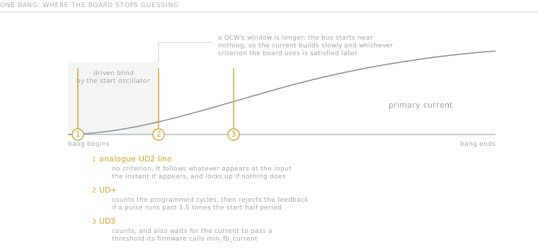
Read the three marks as answers to one question: how long does the board keep guessing. The analogue line does not ask it at all, and the two that do ask it differently.
- UD+ counts, then validates the length of what arrives. After the programmed cycles it looks at the feedback and rejects it if the pulses are too long. Slawinski: "Setting the improper startup frequency can cause the coil to stop switching after the startup cycles have elapsed. This happens when the driver detects pulses longer than 1.5 times the half cycle period for the startup oscillator." A pulse here is a half cycle, so the test trips when the feedback frequency has fallen below two thirds of the start frequency [derived].
- UD3 counts and also measures the current. Its firmware (Netzpfuscher/UD3, Jens Kerrinnes, building on Steve Ward) carries a parameter
min_fb_current, described in the source as "Current at which to switch to feedback". The same routine,configure_ZCD_to_PWMinZCDtoPWM.c, loads the start cycle counter and writes that threshold into a DAC. - The analogue UD2 line has no criterion. The comparator follows whatever appears at its input the moment it appears, and if nothing appears it does nothing. Gao Guangyan's walkthrough of Steve Ward's UD2.7 says that with no input signal in the feedback jacks the driver will not see any feedback, causing the drive to lock up. Nothing in that path asks whether the signal is real, which is exactly why the idle state of the input has to be fixed by hand. On the UD2.7 it is:
R3andR4withC6divide the five volt rail down to a standing offset of about 1.6 V, the feedback is coupled on top of it, and the comparator's own reference is set to the same 1.6 V.
The idle state of the comparator input
Here is the failure, reported by AstRii on a UD+ in June 2024:
sometimes the driver skips an interrupter pulse. It tries to begin pulse but quickly triggers protection of the driver and sets Fault high.
davekni named the mechanism in the first reply, and it is a difference between two boards rather than a fault on either:
Unlike UD2.7, UD+ has no DC bias on FB comparitor input. State between bursts is indeterminant.
The DC bias he means reads as the 1.6 V offset above, documented on one board and said by him to be absent on the other, though the join between his sentence and Gao's schematic walkthrough is ours rather than either man's. Indeterminate is the word to hold on to. The board is not broken and the loop is not mistuned. Between bangs the comparator's input sits nowhere in particular, so its output is high on some bangs and low on others, and on the bangs where it is already high the first push has nothing to change. He offered a patch and disowned it in the same breath:
Not what I'd recommend, but you could patch the issue with a weak pull-down (~100k) on + input of comparitor, forcing idle state low.
AstRii tried it and reported that it "works as a charm". Note what a resistor to ground is doing here. It carries no signal, changes no threshold and does not enter the loop's arithmetic anywhere. It only guarantees that the circuit knows which way it is pointing before the bang begins. Why davekni did not recommend it anyway is the last warning in the next section.
The idle state of the bridge output
The same argument applies at the other end, and davekni has made it on three different coils, in 2020, in 2023 and again in 2024. On a oneTesla TS half bridge rebuilt around a UD2.7, in a December 2020 thread started by a builder posting as David:
One likely issue is that the initial bridge output voltage is already at the same VBus rail that the initial pulse drives it to. Adding a bleed resistor across the opposite IGBT will fix that issue.
Read the sentence that comes before it, because that thread is not only a handover thread. David's coil would not start with the 51 ohm SV1 burden jumper fitted, and the paragraph this sentence sits in begins "Concerning feedback, I suggest replacing the jumper and then figuring out why there isn't enough signal." The reply itself opens on something else again, IGBT failures under hard switching and the parasitic inductance that causes the voltage spikes behind them. The bridge idle state is offered as one likely issue inside an investigation of loop gain. Both kinds of failure are live in the same thread, on the same coil, at the same time. And the self-oscillation recipe quoted in section two is the next paragraph of this same reply, which is where its condition bites: that modification needs SV1 in, and SV1 in is the state this coil would not start in.
On RoamingD's UD2.7 in September 2023, where the mechanism is leakage rather than charge:
Without scope load, if upper IGBT happens to have slightly higher leakage current, output may drift high. Initial start pulse tries to pull it high. If output is already high, no initial change, so no feedback.
And in AstRii's thread, as a design rule rather than a diagnosis: "H-bridge output needs to start centered (0V differential) so that either polarity of initial half-cycle starts oscillation." Which is the second reason for a resistor this corpus already has on the page about the bridge, where it is there to drain residual charge off the tank. Same component, two jobs, and the start-up one is the one that stops the machine dead rather than making it misfire.
AstRii's own bleeder did not fix his fault, which is the useful half of the report: he fitted 22 kilohms across the bridge output against a 50 nF tank, giving what he calls a 1.1 ms time constant, at about 100 bangs per second, and the skipping continued. At that rate the resistor gets roughly nine time constants between bangs [derived], so it had time to do its job. That leaves the comparator input as the remaining candidate, and that is where the fix landed.
How many cycles, and where to put the frequency
The published guidance is one line of the UD3B spec sheet: "The start cycles can in some cases be set to 0 or 1, but most setups work best with at least 2 to 4 start cycles for DRSSTC and up to 8 cycles for QCW." The UD+ sets the same number on four DIP switches, and its table runs from 1 to 15 cycles, with zero reserved for a test mode.
Nobody publishes why a ramp wants more of them, so here is the reading and it is ours: a QCW's bus starts near nothing, so the primary current builds slowly, so whichever criterion the board uses is satisfied later. The blind window is longer because the thing it is waiting for arrives later.
For the frequency, Slawinski gives a bench procedure rather than a calculation. Set the start oscillator as close as possible to the coil's operating frequency; find it by probing primary current and a bridge output and looking for the lowest overshoot; expect to adjust it once the bridge is live. The spec sheet adds the reason the setting has slack in it, from its own note on bench testing a bridge without feedback: the further the drive frequency is from resonance, the slower the primary current builds.
And one negative result worth as much as any of the above. AstRii went looking for his fault in exactly this setting and reported that tuning the start-up frequency helped a little, but that even with it matched to the resonant frequency some pulses were still skipped. The frequency is the second thing to check. The idle state is the first.
The numbers
UD3 firmware defaults, read from cli_common.c. The descriptions of start_freq and start_cycles are the project's own parameter list; those of min_fb_current and max_tr_pw are the CLI help strings from the source, the first because the wiki does not list that parameter at all, the second because the wiki words it its own way:
start_freq       63.0 kHz   "The start oscillator resonant frequency in [kHz]"
start_cycles     3          "Number of start cycles with the internal oscillator"
min_fb_current   25 A       "Current at which to switch to feedback"
ct1_ratio        600 turns
ct1_burden       3.3 ohm    2 W, per the UD3B spec sheet
max_tr_pw        1000 µs    "Maximum TR PW [uSec]"
max_fb_errors    0          off
How long the machine is blind. Start cycles are full cycles on both boards. The UD+ page says so in words, and the UD3 multiplies start_cycles by two before writing it into the zero crossing counter, and a full cycle has two zero crossings. So the blind window is a count of cycles of the bang, and its share of the bang is cycles over cycles, which needs no frequency at all:
3 start cycles at 63.0 kHz                47.6 µs        [derived]
the longest bang the firmware passes
  by default, max_tr_pw 1000 µs,
  at that same 63.0 kHz                   63 cycles      [derived]
3 of those 63                             4.8 per cent   [derived]
That denominator is a ceiling, not a typical bang, and it is the most flattering one available. The fraction rises in exact proportion as the bang gets shorter. AstRii's own test is 170 µs at about a hundred bangs a second, and later in the same thread he models a primary matched to his coil and finds it resonant between 125 and 135 kHz, which puts that bang between 21 and 23 cycles [derived]. Three start cycles would be 13 to 14 per cent of it [derived], and the UD+ dial goes to fifteen, which on a bang that size would be roughly two thirds of it [derived].
And the QCW figure, which this driver will not actually give you. The spec sheet's guidance is up to eight start cycles for a QCW, and that is guidance rather than a default. Against a ramp it vanishes: this corpus's own QCW runs a 25 ms ramp while its frequency slides from 519.1 down to 463.3 kHz, so the ramp holds somewhere between 11,500 and 13,000 cycles [derived], and eight of them is under a tenth of a per cent of it [derived]. But that same 519.1 kHz is a frequency this driver will not accept. start_freq is declared with a range of 0 to 5000 and a display divisor of ten, so the ceiling the CLI enforces is 500.0 kHz and set start_freq 519.1 comes back E:Range. The spec sheet says the same in prose twice, once as experience, "The UD3 has been tested at frequencies of 30khz to 500khz", and once as advice, "This driver is not recommended for applications over 500khz due to this timing resolution limitation." So the QCW row above is arithmetic about a ramp, not about a UD3 driving one.
The handover threshold in volts, from the expression in ZCDtoPWM.c:
25 A / 600 turns x 3.3 ohm = 0.1375 V at the burden [derived]The setting is in amps of primary current and the firmware converts it with the ratio and the burden you have told it about, so changing either of those in the configuration moves the volts and holds the amps. What moves the amps is not telling it: change the ring or swap the burden resistor on the board and leave the configuration alone, and the current at which the handover happens moves by the same factor.
And the resolution, which is coarser than the setting looks. One step of the threshold DAC is 0.016 V, so at that ratio and burden one step is 2.9 A [derived]. The firmware rounds the current limit thresholds and truncates this one, so a min_fb_current of 25 works out at 8.59 steps, is cast to 8, and gives 0.128 V and a real threshold of 23.3 A [derived]. So the setting is an integer number of amps sitting on a 2.9 A grid, the number you typed is not the number it uses, and the error is always downward.
The sensing chain those numbers run through, which this site describes differently. The spec sheet says the lead "is set in software as there is no analog filtering to provide phase lead", so nothing hangs off the feedback transformer. It also says what that transformer is for, "CT: Current transformer input for gate drive synchronization and current limiting", and it rules the other input out of the running: the feedback CT is CT1, and CT2 is for the hall effect sensor and may be omitted. One ring, both jobs.
Two pages here used to say that no UD board does that, and this page is why they no longer do. The reason they gave for two rings is the lead network loading the first stage, and this board has no lead network, so the reason is absent here. Two rings, not one now carries the consequence, which is that sharing forces the sensitivity down, and the case that settles it: Steve Conner shared one ring deliberately in 2006 and published the circuit for doing it, two back-to-back diodes in series with the burden so the feedback tap sees two diode drops more than the protection tap.
And one of the numbers above is this site's own quantity, at a value the site says does not work. Burden over ratio is what these pages call feedback strength, |Z| over N, volts per amp of primary current. At the UD3 defaults it is 3.3 over 600, or 5.5 mV per amp [derived]. The band this site states for that quantity appears five times across three articles as "Working boards sit around 0.02 to 0.04 V/A", and the UD3 default is 3.6 times below the floor of it [derived]. That page now says which rings the band is for: ones that carry feedback and nothing else. Conner's two shared rings sit at 0.010 and 0.0033 V/A [derived], on either side of the UD3, which is what a shared ring costs in sensitivity.
The reading here is ours, and it is a reason rather than a reconciliation: the band is a two ring number and this is a one ring board. The spec sheet gives the current limit comparator a hardware limit of 4.08 V and a maximum current setting of "1.23A*CT-ratio", which at 600 turns is 738 A [derived]. A burden network at 0.02 V/A would reach that same 4.08 V at 204 A [derived]. A ring that has to carry the protection as well as the phase therefore cannot have a feedback strength anywhere near the band, because the band would put the ceiling below the working current. What the live pages state, though, is the band flat, with no such qualifier attached, so one of the two statements has to move and this page does not get to decide which.
What will get you
Read this part before the first start. Three of the four are about the opening cycles of the first bang, and the fourth is about what you do once one of them has bitten.
And one thing that is not a warning, only a fact about testing. Feeding a signal generator into the current transformer input tests the loop and skips the handover entirely, because the signal is there before the bang is. The UD3 wiki describes doing exactly this, with the caution that the input has to be left floating. It is a good test of everything downstream of the sensor. It proves nothing about the start.
What goes wrong
The last two entries are not handover failures at all. They are here because they arrive wearing the same symptom, which is the whole difficulty.
- Bangs are skipped at random, and the fault sets at the very start of the pulse. The comparator's idle state is undefined, so on some bangs the first push commands a state the output is already in. This is AstRii's report and it is a UD+ against a UD2.7 difference, not a defect. A weak pull-down defines it.
- It never starts at all, and the bridge output is sitting at a rail. Charge or device leakage has left the output where the first pulse would put it. A bleeder across the output, or more start cycles.
- It starts only while a scope probe touches the comparator input. The probe is an antenna. Nothing about the coil is fixed.
- Tuning the start frequency helps a little and does not cure it. The frequency is not what is wrong. An idle state does not improve gradually.
- The coil runs, and the running frequency is exactly the number you typed. The handover never happened. On a UD3 that is silent by default: the threshold may be above anything the first cycles reach, or the transformer may be dead or reversed.
- It stops switching cleanly, just after the start cycles end. On a UD+ that is the validity test rejecting what arrived, because the pulses coming back are longer than 1.5 times the start oscillator's half cycle. Slawinski names this one directly, and the cure is the start frequency.
- Faults during a frequency sweep, which then stop. Expected. The UD3's tune command deliberately turns the handover off for the duration: the source sets
start_cyclesandmax_fb_errorsto zero with the comment "set configuration of fb current detector to ignore missing feedback", and raisesmin_fb_currentto the maximum transient current so feedback never engages. The sweep walks 128 frequency steps, so at the default of one sample each it is 128 open loop shots on purpose [derived fromROWSandautotune_s]. - It will not start, and the signal at the comparator is small. Not the handover. This is loop gain, and it is what davekni went after first in the 2020 thread above, with the burden jumper back in place. The question there is why there is not enough signal, and the answers are the transformer, its ratio and its burden rather than any of the settings on this page.
- A clone will not start on settings copied from a UD2.7 thread. Also loop gain: the feedback diodes were changed and the signal has to be bigger before anything oscillates. That is on the UD boards page.
Where next
- Inside the driver, the four jobs this one is the first few microseconds of.
- Two rings, not one, the sensor that has nothing to sense until the current is there, and the page this one disagrees with twice.
- The bridge and what kills it, where the output bleeder lives and why it is a power part.
- Converting a DRSSTC driver, which is the other answer to this page: a driver that self-oscillates never has a handover, because it was never waiting.
- The two poles, because the frequency the start oscillator has to be near is not the one you measured on the secondary.
The start path is not a box on any department diagram. It lives inside the driver, between the interrupter's edge and the first thing the current transformer says. Every figure above is either quoted from the firmware and its own documentation or marked as derived with its inputs beside it, and where the reasoning is this corpus's rather than a builder's, the text says so.
- Self-oscillation frequency gives the free-running frequency the board starts at, which is the one thing this page says the loop cannot ask the machine for.