A small ferrite ring with a few turns on it, sitting between the driver and the bridge. It exists because of one awkward fact about the top half of a bridge. On a Tesla coil bridge the top devices have their emitters on a node that swings by hundreds of volts.
What a gate drive transformer is, and why the signal goes across magnetically
In a bridge, the bottom transistors have their emitters connected to the negative rail, which stays put. You can drive their gates from logic that shares that ground.
The top ones do not. Their emitters are connected to the output node, which is the thing that swings from the bottom rail to the top rail hundreds of thousands of times a second. A gate has to be driven relative to its own emitter, so driving the top devices means driving something that is moving by hundreds of volts.
You cannot wire logic to that. So the signal goes across magnetically: one winding on the driver's side, one per device on the bridge's side, no electrical connection between them. That is the gate drive transformer.
And why a transformer rather than an opto-isolator: speed. The edges have to arrive in well under 200 nanoseconds, and they have to carry real current, because a gate is a capacitor of several nanofarads and charging it quickly is what turning the device on quickly means. A transformer does both without needing a power supply on the far side, which matters when the far side is floating.
What you decide: core, turns, wire and winding direction
Almost all of it is construction, and every choice here shows up directly as the shape of the waveform at the gate.
The core
Two criteria, and the "frequency range" line on a datasheet is not one of them.
Permeability sets the turns. Turns go as one over the square root of µ, so a core with half the permeability wants about forty per cent more of them.
Hot B_sat sets the saturation margin, and hot is the word that matters: the cold figure on the front page is not the one to design against. How much it falls by 100 °C depends on the material and it is not one number, a fifth to a quarter on the power ferrites, and past a third on the high permeability ones: the N30 example at the end of this page loses 37 per cent, from 0.38 T to 0.24. Both of those are TDK's own figures for the material, printed one under the other: BS (25 °C) 380 mT and BS (100 °C) 240 mT (SIFERRIT material N30), and the 37 per cent is the step between them [derived, 140/380]. This line used to cap that at a third, which its own worked figure exceeds. Take it off the curve for the part you actually have.
An ungapped ferrite ring. Powdered iron is worse; the nanocrystalline alloys are better at both criteria and cost accordingly. Gapping costs you the magnetising inductance you need and buys nothing here.
What the number does mean is where the permeability starts falling, and Snoek's limit puts that at roughly 1500 to 2000 divided by µi, in megahertz:
f_rolloff [MHz] ~= K / mu_i
K = 1500...2000
Which is not a wall either. Past it µ declines gradually and the losses climb, the part still works, and the practical consequence is narrow: the effective A_L is below the low frequency catalogue figure, so the sag comes out worse than the arithmetic said.
All of which assumes you know what the core is. Half the good ones on a coil came out of a dead switching supply and arrived with no marking, no datasheet and no A_L, and A_L is the term the entire turns calculation stands on. It takes two minutes to find out.
One thing to know before you start unsoldering, though, because it decides which part you take. The main transformer in a switching supply is almost always gapped, usually as a ground face on the centre limb, because that is what stops a flyback core saturating under its DC. Gapped is the one thing said above that a gate drive transformer cannot use. The part you actually want out of that supply is the common-mode choke: a ring, ungapped, high permeability, wound as pairs, built for exactly the job you are about to give it. That is our reading of what those parts are for rather than a recommendation from a source, but the measurement below settles it either way.
And one criterion that only exists because of how a coil runs. Every treatment of gate transformer saturation, this page's included until here, assumes continuous operation. A coil does not run continuously. It runs in bursts, and a burst that ends anywhere other than at zero flux leaves the core sitting at its remanence B_r, so the next burst does not start from the middle of the available swing, it starts offset, with the headroom in one direction short by that much.
A last mechanical one, which is not electrical at all. Do not clamp the ring hard. Ferrite is brittle and a bolt through a clamp will crack it, and short of cracking, mechanical stress changes the magnetic properties of the thing you just measured. Hold it with a cable tie, a bed of silicone, or a printed cradle that does not squeeze. This is ordinary practice with ferrite rather than something our sources say about gate transformers specifically.
The turns
Two conditions set the turns, and they scale differently with frequency, which is why which one is binding changes as you go up the band:
by inductance
  N >= sqrt(10·t_on·R_loop / A_L)
  grows as sqrt(t_on)

by saturation
  N >= V·t_on / (B_sat·A_e)
  grows as t_on
The 10 is not a constant. It is a sag tolerance with the arithmetic already done, and knowing that is what lets you move it. TI's condition is that the droop over an on-time is some fraction d of the supply:
V_droop / V_supply = t_on·R / (2·L_mag)  <=  d

so  L_mag >= t_on·R / (2d)
and the factor is 1/(2d)

d = 5%  -> 10        d = 10% -> 5
d = 2%  -> 25
So the formula above is the five per cent condition and nothing else, and since turns go as the square root of the factor, a tolerance you can live with is directly a winding you can fit.
The saturation term there is deliberately pessimistic by a factor of two, and you should know it is, so you do not add a second safety factor on top of ours. A push-pull transformer driven symmetrically walks the flux from −B_sat to +B_sat, so the excursion actually available is 2·B_sat and the honest denominator is twice what is written. We keep the one-sided form because nothing holds the duty cycle exactly symmetric: any imbalance leaves a DC component that walks the operating point off centre and eats the other half of the headroom. The factor of two is the margin for that, not a term in the physics.
The saturation condition falls away faster. Worked across the band in turns, our arithmetic in both columns, and the inputs are worth naming because they do not all come off one machine. The inductance column is 11.5 Ω of loop resistance into an A_L of 4000; the saturation column is a 24 V gate drive against davekni's 95.8 mm² core at the 0.24 T hot figure worked at the end of this page. His example states neither the drive voltage nor the loop, so the 24 V is the ordinary figure this page uses elsewhere for Burnett's sag and not his. The waveform page refuses to print a turn count off that example for exactly this reason and sends the reader here: this is the composite it was declining to make, and it is why the trend below is worth more than the digits.
- 50 kHz: 17.0 by inductance, 10.4 by saturation.
- 250 kHz: 7.6 and 2.1.
- 460 kHz: 5.6 and 1.1.
Inductance is the binding one throughout, but saturation closes on it as the frequency falls and is irrelevant at the top. Which is the arithmetic behind the thing that reads backwards: a core saturates on a big slow coil, not on a fast one.
So on any coil worth the name the turns are set by sag, not by saturation. Under about thirty per winding, in a single layer. Sag on the top or bottom of the waveform is the signal that there are not enough; up to about 2 V of it is acceptable.
How the wire is laid
Criterion: leakage inductance, which is what rings.
Wound as tightly twisted pairs, each secondary wire paired with its own primary wire, all lying in one layer. Separate windings on opposite sides of the ring leak badly and give overshoot.
Tight is not the fault. Twisting is what shrinks the loop between the two conductors, and that loop is what leakage is made of, so tighter keeps helping until the extra wire costs more than the smaller loop saves. What it costs is length, and length is the thing to watch: at two diameters of pitch the wire runs eighty-six per cent longer than straight, which is resistance, and it is also wire that has to fit in one layer.
1 · Too few turns
Sag on the top and the bottom
Magnetising current too high. The core saturates before the half cycle is over, and it buzzes.
2 · Windings apart
Low frequency ringing and overshoot
Leakage. A damper does not fix it; rewinding as pairs does.
3 · Too many turns
Slow, rounded edges
Long wire: leakage and capacitance between turns both up. Top still flat.
4 · What good looks like
Flat top, steep edges, one small overshoot
Edges under 200 ns and nothing after the overshoot. The turns that get you here depend on the core.
How many
The count is set by how the bridge is modulated, not by how big it is. This page said "one per leg is normal" and that was wrong, generalised from one board's arrangement.
- Ordinary drive, the legs held hard in antiphase: one transformer for the whole bridge, and that is the norm rather than a compromise.
- Legs that have to be driven independently: two. That means freewheeling, where the devices turn off in turn rather than together, and phase shift, where the modulation depth is the shift between the legs.
- More than one bridge: one per bridge is the usual answer rather than a rule. Gao ran his eight-device dual bridge off two cores in 2014 and off a single large one a year later, with nothing about the bridge changing in between.
Gao's own machines show the fork. He publishes as loneoceans, and the two names are one person, which is worth saying once because both are quoted in this corpus. QCW 1, in 2013, is a full bridge of four IGBTs on one transformer, wound by wrapping the core in Ethernet cable. Then the count moves twice on the same coil and never because of size. The 2014 rebuild doubles the bridge to eight devices and goes to two cores, "two GDTs with a 6:5 primary : secondary ratio"; and QCW 1.5 keeps that same bridge and rewinds "the GDT to use a single large GDT core". One core for four devices, two cores for eight, one core for eight, one builder. And when he moved to phase shift on QCW 2 he needed the legs apart. Slawinski's UD+ runs two, one per leg, because it freewheels: "In order for freewheeling to work you must use two separate GDTs. Each GDT will be connected to one of the GDT outputs on the UD+. Each of the GDTs controls a half bridge".
And there is a second cost to one core, which the modulation argument above does not cover and which is easy to miss because it only appears once something else has already failed. A shorted gate is a shorted secondary, and a shorted secondary reflects into the primary as a short. On a shared core, one device failing gate-to-emitter therefore takes the drive away from the other three: instead of one dead transistor you have a bridge in which nobody turns on properly, and the second failure follows from the first rather than from whatever caused it. Separate cores confine that. It is not a reason to wind four cores for an ordinary bridge, the modulation argument still decides, but it is what you are buying when you do, and the answer to "what does one core actually cost me" is this and not the waveform.
The trick that makes twisted pairs trivial
Gao winds the secondaries with a length of Ethernet cable, which as he puts it conveniently has eight wires inside already.
And there is a second trick for when you have no Ethernet cable, which solves the same problem with plain hookup wire. What the cable buys you is not the twisting, which you can do yourself, but the colour coding: after twisting, you still know which end of each wire is which. 山猫 gets the same thing from lead length. Cut each wire so one end runs short and one runs long, call the short one A and the long one B, and then twist: "由于前面已经用引线的长短标记出来了 同名端,做成双绞线也不会乱", since the dot ends have already been marked by the length of the leads, making them into twisted pairs will not confuse them (hvdiy 235771).
His whole recipe is four lines long and is aimed at one core doing both jobs, "大小功率桥通吃", swallowing bridges large and small alike:
core       ferrite toroid, OD 49 mm, ID 32 mm, height 19 mm
secondary  4 wires of 0.3 mm2, wound four in hand, 13 turns
primary    0.4 mm2
tested on  a G4PC50UD full bridge and a CM300DY-24H full bridge, both at 50 kHz
Those areas are the Chinese standard sizes and come to roughly AWG 22 and AWG 21 [derived]. Read the whole of it as one builder's working part rather than as a specification: he publishes no A_L, no measured magnetising inductance and no volt-second calculation, so the thirteen turns are his core's answer and not a number to carry to yours. What does transfer is the marking trick, which costs nothing and works on any wire.
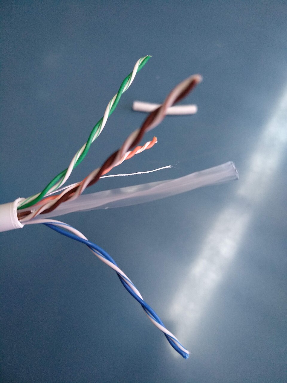
It is a better answer than hand winding rather than a lazier one, and the photograph shows why in three ways.
Eight wires, already paired. A full bridge wants four pairs, one per device: one wire of each goes to the primary and the other is that device's secondary. A single length of cable is exactly that, in the right count, with the pairing already made and impossible to get wrong by picking up the wrong strand.
And that parallel connection is doing more than fixing the ratio, which is the part worth understanding rather than just obeying. The primary current splits four ways, so each conductor carries a quarter of it, while each secondary still sits against its own primary wire down the whole length of the pair. That is the real reason the cable trick is good: not only that the twist is tight, but that every gate is coupled to a conductor of its own instead of all four sharing one. Four small tightly-coupled transformers, laid in one sheath, on one core.
One path inside one sheath. The two wires of a pair never separate, over the whole run, which is what the section above spends its numbers on: the loop between them is as small as the geometry allows and stays that way at every point, rather than at the places you remembered to twist.
A factory pitch, held. The twist is even along the entire length, which is something nobody achieves by hand, and it sits in the tight part of the ladder above without the pair ever coming apart.
Which way round each winding goes
The section above decides how many cores. This one decides which end of each wire goes where, and it is the mistake that costs a bridge on first power-up.
The two devices in a leg are driven in antiphase. On one core that means their secondaries are wound opposing: start of one to the gate, start of the other to the emitter of its opposite. Get one pair the wrong way round and both devices in that leg turn on together, which is a short across the bus through two transistors.
Winding it as pairs makes this easier rather than harder: one wire of each pair goes to the primary, start to start and tail to tail, and the other is that device's secondary. Turning the whole core over is the ten-second test if the feedback comes out wrong.
And you do not have to find out on the bridge. Terminate every secondary into something that looks like a gate (a resistor of the gate resistor's value in series with a capacitor of roughly C_iss, which for these purposes is a ceramic of the right order and not a precision part), drive the primary from the real driver at the real frequency, and put the scope across all of them in turn. A reversed winding is not subtle on that bench: it is the trace that is upside down next to its neighbour, at no volts and no risk. Four traces that agree is also the cheapest confirmation that the four windings really are identical, which is the assumption the whole single-core arrangement rests on. That is our suggestion rather than a procedure from a source, but it costs two components per gate and it is the same four traces you would otherwise be reading after the bang.
What the driver is actually driving
Not a transformer. A transformer plus every gate hanging off it, and the two loads behave nothing like each other.
driver current
  = magnetising    (N, mu, A_e)
  + gate charge    (C_iss, ratio,
                    edge wanted)
The magnetising part is the one you chose when you picked the turns. It goes down as N², so the same core with a third more turns asks the driver for about half as much of it. That is the fourth face of the same trade: fewer turns couple better and leak less, more turns sag less and load the driver less, and the answer is a compromise rather than an optimum.
The gate part is not negotiable at all. A gate is a capacitor of several nanofarads and the edge you want decides the current: charge divided by time. This is where the ratio bites, and it bites as a square.
And on a ramped coil neither term is a burst any more. Over a bang of tens of milliseconds the gate charge has to be counted over the full swing, both devices in a leg, twice a cycle, for the whole ramp, and it comes out in amps average and millifarads of reservoir. That is a supply, not decoupling.
The one resistor that is part of this transformer
There are half a dozen resistors around a gate drive and they get confused with each other constantly. Exactly one of them belongs to this page, because exactly one of them appears in the arithmetic above.
The damping resistor in the primary loop is the one to think about hardest, because it is not free in the way it looks. It sits inside the inductance condition, so it does not buy damping with money, it buys damping with turns: ten ohms costs 1.37 times the turns and thirty costs 1.90, and the extra wire brings back the leakage you wound the thing carefully to avoid. It is also what dissipates the DC that asymmetric duty leaves on the winding, so it cannot go to zero either. Not zero, and nothing spare, which is an unusual shape for a component specification and is the reason this one gets its own paragraph.
Everything else at that end of the drawing lives elsewhere, and the split is by what you are doing rather than by how close the part sits to the ring:
- The gate resistor, the diode across it, a PNP local turn-off and its
R_B, and what the negative bias costs are all one circuit, the loop between the gate and its own emitter, and they are on the gate loop's page, along with the ferrite beads, which cure an oscillation rather than a ring and are not a substitute for either. - The pull-down, the TVS and UVLO are protection: what holds a gate down when the drive is absent, wrong, or being fought by
dV/dt. Three cases, three different answers, and they are with the driver. - The current transformer burdens and the two bleeders are not part of the gate drive at all. They are here in a repair only because they sit near it on the board, so they are with the diagnosis.
What loads it that is not a resistor at all
- Capacitance to the switching node. With a ground plane under the transformer, that capacitance plus the ground wire's inductance is a parasitic resonator. This is why the layout rule is no plane there.
- Capacitance between the windings, which is not a general transformer complaint but a property of this one: a push-pull gate transformer has noticeably more of it than a power transformer, and it is the path by which the switching node reaches back to the driver.
- The leads. A gate drive transformer's own leads usually carry more inductance than anything on the board, which is why this is a construction problem and not a routing problem.
- Solid against stranded wire, which is very nearly nothing. Twist and lead length are the terms that matter.
Whether to use one at all
The page opened by comparing this against an opto-isolator, and that comparison was settled a decade ago. The live one is an isolated gate driver with an isolated DC-DC supply per floating rail: the UCC21520 class of part, or the capacitive and magnetic isolators next to it. If you have not costed that out, you are choosing a gate transformer by habit rather than by decision.
What the driver gives you is everything the ring is bad at. There is no volt-second limit, so duty cycle is yours down to DC, which is exactly the buck-modulator case below. The propagation delay is a datasheet number rather than a property of your winding. Desaturation detection, an active Miller clamp, and interlock come in the same package, and the Miller clamp is the honest answer to the dV/dt problem this article can otherwise only tell you to keep your loop short about.
What keeps the transformer in the running is that it carries the power as well as the signal. One passive part replaces a driver, an isolated supply, its decoupling and its own protection, on every floating gate, and that supply is a real supply on a ramped coil, not a trivial part of the job. It has no silicon sitting at the switching node to lose, it cannot be desynchronised by a common-mode edge because it has no logic to upset, and a spare can be wound in ten minutes at two in the morning out of wire you already have. On a coil the last of those is not a joke.
What will get you: where the gate resistor goes, and what to probe
And the resistors and the turns are one problem, not two. Loop resistance is in the inductance condition, so anything added to it puts the turns up: ten ohms costs 1.37 times the turns, thirty ohms costs 1.90. More turns is more wire, and more wire is more leakage. Reach for a resistor to damp the ringing and you get the ringing back from the other end, which is the quantitative version of the warning above.
And no ground plane under it. Capacitance to the switching node plus the inductance of the ground wire makes a parasitic resonator. It is a layout rule rather than a way to lose hardware, which is why it is not marked as one: the phasing above is.
The duty cycle has to be nearly symmetrical. The average voltage across the transformer must be zero, or direct current in the primary loop climbs until the core saturates. TI states the requirement plainly, and notes that the loop resistance is what gives you any margin at all, by dissipating the excess: the same resistance the turns arithmetic is built on.
For a Tesla coil this is free, because a resonant bridge runs at nearly fifty per cent by construction. It is also why a gate drive transformer is the wrong way to drive a buck modulator's switch, where the duty cycle is the control variable. Doing it anyway means a blocking capacitor on the primary and a DC-restoration network on the secondary, which is enough extra parts that another isolation method is usually the better answer.
And the one that reads backwards. A saturated core stops passing the signal, and it is natural to assume that running faster makes saturation more likely. It is the other way round. Saturation is a volt-second problem: the faster the switching, the shorter each half cycle, so the fewer volt-seconds are applied per transition. The risk is at the low frequency end. Big slow coils in the tens of kilohertz are where gate transformers saturate, and a saturated one is audible as a loud buzz.
The one measurement that passes or fails
Everything above says what to aim for. This says whether you got there, with a number, on the assembled bridge and before it is carrying anything.
The thresholds are the ones the corpus works to. Why they sit there is our reading of them rather than anybody's stated rationale: a gate threshold is a few volts, so pickup that reaches five is not a margin problem any more, it is the device beginning to turn on while its opposite is on, and three leaves room for the part of it that is worse at full bus than at the bus you tested at.
The numbers: ratio, turns, core and inductance
- Ratio: 1:1 usually, sometimes 1:1.5 or 1:2. A non-unity ratio loads the driver as the square of it.
- Turns: under about thirty per winding.
- Core: ungapped, and enough
A_Lthat the inductance condition lands on a turn count you can fit in one layer, with roll-off left over at your frequency. Deliberately not a permeability threshold. This line used to read "µrover 4000", which is inherited from general gate-transformer advice and contradicts the rest of this page: PC40 is 2300 and Fair-Rite 77 is 2000, so that threshold rules out both of the cores recommended here in favour of the one described as sitting on its own edge. Permeability is a term in the turns, not a specification to buy against. - Edges to aim at: under 200 ns rise and fall. Worth knowing what that is competing against: at 460 kHz a half cycle is 1.09 µs, so 200 ns is nearly a fifth of it at each end. What sets it is
t = Q_g / I_drivewhile the driver is the limit (halve the edge by doubling the current, and a device with twice the gate charge wants twice the driver) and the leakage inductance once it is not, becausedi/dt = V/L_leakagedoes not care how much current the driver could have supplied. The tell for which regime you are in is whether a bigger driver chip changes anything. If it does not, you are rewinding, not reordering parts. - Delay through the transformer itself: effectively zero. TI puts it as the signal crossing at the speed of light and says it can be treated as 0, so the total is the driver chip's delay plus whatever the secondary-side parts add. The transformer is not a term in the phase lead budget, and somebody hunting nanoseconds inside it is looking in the one place they are not.
- Acceptable sag: up to about 2 V on the scope, against a design target of 5 per cent, which is the pair discussed under the turns.
- Volt-seconds available: core area ×
B_sat, and it has to cover the half cycle. One-sided on purpose: the swing a symmetric drive can really use is2·B_sat, and the factor of two is being held back against duty imbalance rather than spent. Worked, and this one is davekni's, off a real coil at about 240 kHz: 95.8 mm² at 0.22 T is 21 µV·s per turn, which at a 2.1 µs half cycle allows up to 10 V per turn [derived from his core area and that 0.22 T]. Two separate things pull it down from the datasheet's 0.38. The first is heat, and it is the larger: a high permeability core loses about 37 per cent by 100 °C, which lands on 0.24 T and is the same hot figure the N30 row below carries, TDK'sBS (100 °C)of 240 mT (SIFERRIT material N30). The second is his own margin, another 8 per cent under that, and it is a choice rather than a property [derived]. Rebuilding the example from 0.24 gives 23 µV·s per turn and 11 V per turn, which is what the saturation-turns list further down reproduces at. A power ferrite loses nearer a fifth to heat.
Cores, as turns needed where a 4300 core takes 6, with the roll-off from Snoek and the margin that leaves at 460 kHz:
- N30,
µi4300, hotB_sat240 mT: 6 turns, roll-off 349 to 465 kHz, margin 1.01. The classic for gate transformers and current transformers, and at this frequency it is sitting on its own edge. - PC40, 2300, 380 mT: 8.2 turns, roll-off 652 to 870 kHz, margin 1.89. The core out of every dismantled switching supply, so the easiest one to find, and on volt-seconds it beats N30 outright.
- Fair-Rite 77, 2000, about 340 mT: 8.8 turns, roll-off 750 to 1000 kHz, margin 2.17. Recommended in the community for gate and current transformers on small and medium DRSSTCs.
- N87, 2200, 8.4 turns, roll-off 682 to 909 kHz, margin 1.98. The standard part.
- N95, 3000: 7.2 turns. Even over temperature.
- N41, 2800: 7.4 turns. TDK marks this one as a current transformer.
- N49, 1500: 10.2 turns, roll-off 1.0 to 1.33 MHz, margin 2.90.
- PC200, 800: 13.9 turns.
- Nanocrystalline, up to 80 000,
B_sat1200 mT: 1.4, so take 2 or 3. Best on both criteria and priced accordingly. Ribbon, wound from tape, and not the powder of the same name: nanocrystalline powder cores are a separate product with a distributed gap and a permeability two orders lower, and they belong to choosing a choke core rather than here. Carrying 80 000 from this row into that calculation is the shape of mistake this page is otherwise built to prevent.
The turns column is 6 × sqrt(4300/µi) and the roll-off is Snoek; both are our arithmetic on published permeabilities [derived, the whole ladder]. The check that it is not invented: N30's computed roll-off, 349 to 465 kHz, lands on the 400 kHz where TDK's own optimal range ends, and that 400 kHz is printed rather than inferred: the material sheet gives the optimum frequency range as fmin 0.01 MHz and fmax 0.40 MHz (SIFERRIT material N30). The same sheet is where N30's µi of 4300 and its 240 mT hot come from. PC40's µi of 2300 and its 380 mT are TDK's too, the Bs row at 100 °C in the material characteristics list, against 500 mT at 25 °C on the line above it.
What a resistor in the primary loop costs, in turns, from the inductance condition at 460 kHz:
- 11.5 Ω, the loop as it stands: 5.6 turns.
- plus 10 Ω: 7.6 turns, 1.37 times [derived, this list].
- plus 30 Ω: 10.6 turns, 1.90 times.
What goes wrong, and what each symptom means
The four windings above are the four ways it goes wrong, and the fourth is the one to hold your own trace against. What that section does not say is under what conditions to capture yours, and getting that wrong wastes the comparison.
Take the trace with bus voltage on. The Miller plateau is the gate charging the Miller capacitance while the switching node swings, so with no bus there is no swing and no plateau. What that does not give you is a threshold, and this page used to run two unrelated figures together as one and call them agreed. They are not the same claim: 30 to 50 V is Burnett's floor for a check worth taking, and 100 or more is Barnkob's caution about how much worse a bridge transient looks at low collector voltage, which is the other node entirely. The waveform's own page keeps them apart. No published figure says where the plateau starts to be representative. A trace at no volts still shows sag and it still shows leakage ringing, but it cannot show you anything the switching node does, and that is where the expensive faults live. It is also why the pass-or-fail measurement above is specified with the bus coming up rather than at the bench.
The rest of the symptoms appear on the same trace and their cures are mutually exclusive too, which is why they have a page of their own. In short: low frequency ringing is leakage and wants rewinding, high frequency ringing wants damping, rounded edges want less damping, and sag wants more turns. Reaching for a damping resistor when the fault is leakage is the usual first move and it makes things worse.
Where next
- Reading a gate waveform, the diagnosis in full.
- The gate loop is an RLC, on choosing the gate resistor, which is tangled up with this transformer's leakage.
- The gate supply on a ramped coil, where all this stops being a decoupling problem.
The gate transformer on the department diagrams is drawn as one wound core per leg, which is the arrangement a freewheeling driver needs and not the only one there is. The gates come down into it from above and the driver comes up from below; nothing is threaded through it.