The coil rings at hundreds of kilohertz and nobody can hear it. The interrupter switches it on and off at an audible rate. That is where the note comes from, and all the music with it.
What it is and why
Bangs per second is the frequency of the note in hertz: 200 bangs a second is 200 Hz. Ontime is how long each one lasts.
duty = ontime × bangs per secondThe average power stays tolerable while the peak goes up many times over. At 5 per cent duty each bang can carry twenty times the power, and that is the whole reason a coil is interrupted rather than run flat out.
There is no best rate. It is a note.
What you decide
The rate
Criterion: average power, which is the rate times the ontime. A higher rate wants margin in RMS current and in heatsinking, and buys you a higher note and nothing else.
The ontime, and why too short is also a mistake
A doubly resonant coil is not a spark gap coil. The energy does not all leave in some transfer time; it is pumped in across the whole bang. So a longer ontime gives a longer spark, and it does so most clearly at modest peak currents. Shortening the ontime does limit the primary current, for that same reason. But at modest peak currents there is nothing to be saved from, and setting it short "to be safe" costs length and buys nothing back.
The gap between bangs
Set it to the fall time of the primary current, which is a thing to look at on a scope rather than guess. That is the floor, and there is a ceiling above it. Both arrive in one answer from TMaxElectronics, written to Felix B., who was leaving 300 µs between interrupter pulses:
From my experiments deadtimes above 30us start to become noticeable as noise on the sound. What I'd recommend you do in order to set the deadtime is to scope your primary current and set it to the time it takes to decay after an interrupter pulse. Then there is no risk of hard switching at the start of the interrupter pulse.
The sentence after the number is the one that makes those a window rather than two rules pulling against each other. Under the fall time, the next bang starts while current is still in the primary and the bridge switches into it hard. Over about 30 µs, you hear the gap. Anywhere in between, the setting is not doing anything to you.
Whether to run staccato
Tying the bangs to the mains zero crossing. Three practical notes:
- Use a CMOS 555. A plain NE555 draws a shoot-through spike and makes a mess of its own supply.
- The trigger wants a fast falling edge near zero, a couple of microseconds wide: a Schmitt trigger and a small capacitor.
- With the bridge connected the rectified voltage never reaches zero and the detector stops working. Fit a separate half-wave diode with a bleeder and no capacitors, purely for the zero detection.
What one actually looks like
Small, analogue and cheap, on the evidence of what gets published. xionglongztz puts a whole one on OSHWHub: two NE555 and an LM393 on a 60 by 80 mm board off 12 V, with the output on an ST multimode fibre connector. One 555 makes the square wave and the other sets the duty; the comparator is there for the second mode, which is audio in on a 3.5 mm jack with channel select, so the same box either runs at a rate you set or plays what you feed it. Low frequency pulse and long pulse are switches on the side.
Two things to take from it rather than the part numbers. The fibre is not an option on that board, it is the output, which is the fail-safe rule built into the layout rather than bolted onto it. And there is no microcontroller in it at all, which is ordinary in Chinese practice rather than a compromise.
And here is one of the same class with its circuit published. Daniel Marks' board in the DRSSTC PCB Pack is Steve Ward's burst mode interrupter with an external sound trigger added, and it is under a licence that lets the drawing be printed here rather than only linked.
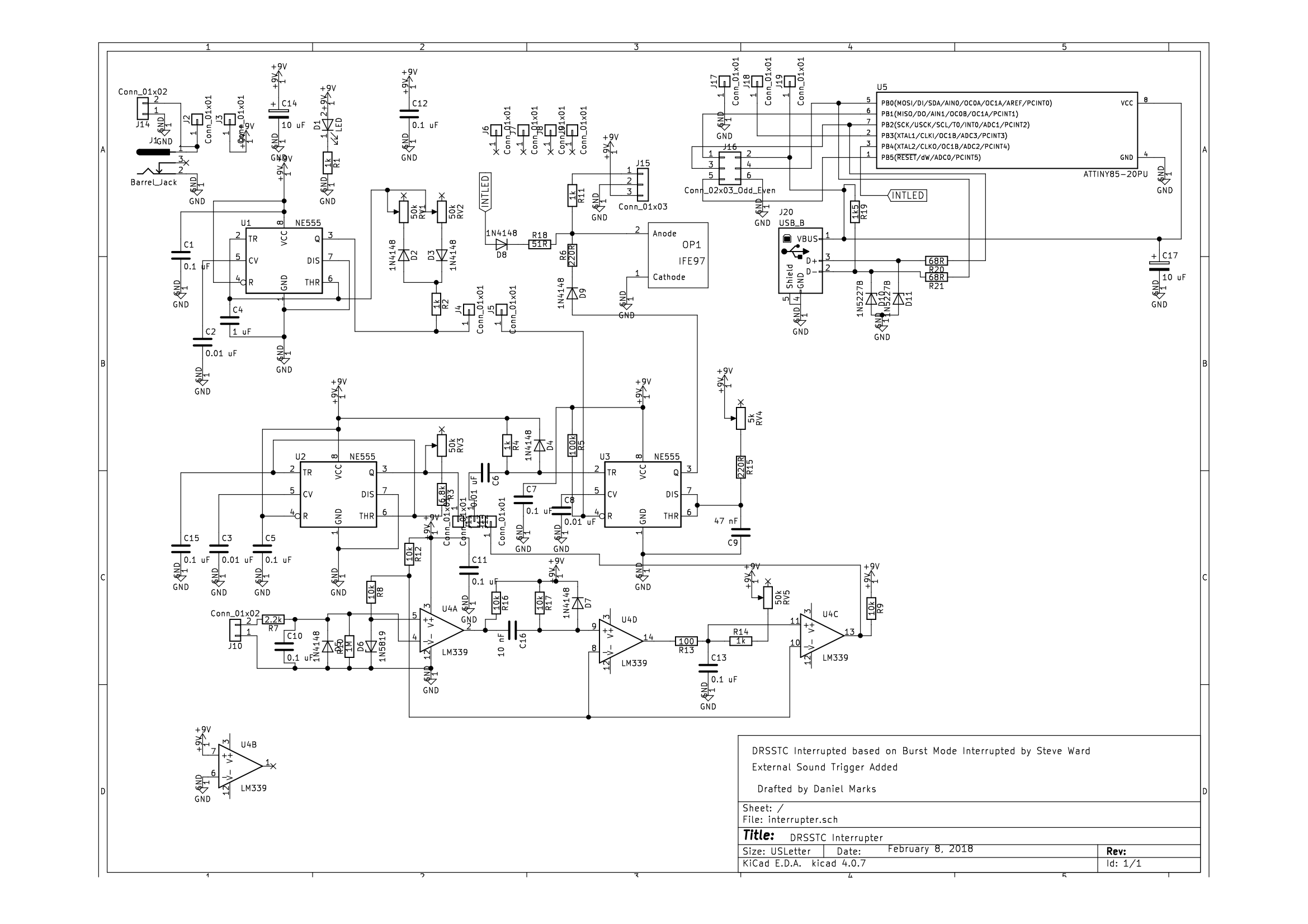
Read it against the Chinese board and the skeleton is the same one. Timers making the pulse train, a comparator on an audio input, a fibre transmitter as the output rather than as an option. Two differences are worth the space:
- The microcontroller is beside the analogue chain rather than instead of it. The sheet carries an ATtiny85 with a USB socket and a programming header, for the oneTesla MIDI code, and it carries three NE555s. Both paths end at the same fibre LED. So the line this page drew between a board with a micro and a board without one is not the line the boards themselves draw.
- One of the timers has its mark and its space on separate trimmers.
RV1andRV2charge and discharge the same 1 µF through opposed 1N4148s, which is how you get rate and ontime as two knobs instead of one knob and a compromise. Those are the two numbers at the top of this page, and this is what they look like as parts.
What will get you
And the link to the coil has one rule that is not about music at all: a broken fibre must turn the coil off, not leave it on, and the receiver does not do that by itself. That is the fibre and the fail-safe rule, and it is worth reading before the first MIDI file rather than after.
The numbers
- A note: bangs per second in hertz. 200 bangs a second is 200 Hz.
- MIDI ontime: typically no more than about 300 µs a note.
- The gap between bangs: the fall time of the primary current at the bottom, about 30 µs at the top (TMaxElectronics).
- Duty: ontime times rate, summed over voices.
- At 5 per cent duty: each bang can carry about twenty times the average power.
About the sound, honestly. It is a train of square pulses with a great many harmonics: recognisable, but metallic, and the range is narrow. The timbre follows the size of the coil, so a ten centimetre coil sounds like a wasp and a metre one sounds impressive on the same MIDI file. For real music out of plasma people go to HFSSTC.
What goes wrong
- Devices die during a particular piece of music and not others. The summed duty of the voices. Scale the ontime in firmware.
- Audible noise between notes. The gap between bangs is over about 30 µs. Shorten it towards the fall time of the primary current, not below.
- The arc looks disappointing. Test in the dark. In daylight the arc is pale and you will undersell your own result.
- A staccato trigger that stops working once the bridge is connected. The rectified voltage no longer reaches zero. Separate half-wave diode.
- Shorter arcs after shortening the ontime for safety. Working as described. The energy is pumped across the whole bang.
Where next
- The fibre and the fail-safe rule.
- The bridge and what kills it, since the two settings above are the two that get it.
- The shape of the ramp, where the same box does a different job.
On a QCW there is no interrupter as such. The box in that position tells the bridge when to run and tells the buck what voltage to hold while it does, and the second of those is the ramp. Bangs per second there is five to seven rather than hundreds, and there is no ontime of its own: the bridge runs for exactly as long as the ramp lasts. The interrupter is a box on the DRSSTC diagram with the two knobs under it that it actually sets; on the QCW page the same box is a modulator, with a line running up the outside to the buck.