Arcs consistently above three metres, the longest recorded at 318 cm, off a 16.4 cm winding of 28 AWG. The winding figure was corrected downward after he modelled it. Among the highest ratios on the wall. Daniël Eindhoven's RAIKIRI runs the APWM scheme he worked out here, in a full bridge, to 350 cm. It hangs below this card as the first of that family.
The 2024 driver is a self-oscillating comparator design of his own. It uses an MCP6562-based Schmitt-trigger integrator oscillator, with injection-locked phase lead read off the primary current transformer. Overcurrent shutdown and a synchronous-disable latch are built from 74HC74s. Isolated half-bridge gate drive goes through a 2EDx9259-family driver IC, and a bus-voltage zero-crossing sensor times the start and stop. A separate, longer thread of his on induction heaters, posted on and off since January 2015, is the one he explicitly flagged as applicable to future “QCW Tesla Coils” work. It started plain: an IGBT full bridge with a 4046 PLL and pulse-skip power control, and no SiC. SiC came in around a year later, once he was already building SiC converters professionally. By 2022 the thread had reached a PSFB (phase-shift full-bridge) design around a UCC3895 controller, with its own isolated gate-drive booster board. That architecture, and not this half-bridge, is what scales up into QCW II below. All schematics for both the 2024 and 2022 boards are his own KiCad work, posted with the builds.
Two results from later in the thread. Coupling decided the coil. Moving k from 0.38 to 0.48 gave what he calls a dramatic improvement in arc length per amp of primary current. He notes that APWM coils are a little more forgiving of tuning the primary below the secondary, because they already run with some leading phase to hold ZVS. When he finally measured his own bus, the impedance peak between the bulk electrolytics and the bridge sat at 50 kHz (about 500 nH of stray inductance), half an ohm at the peak. So a 200 A overcurrent trip rings the bus by roughly 100 V. More local decoupling moves that peak down in both frequency and magnitude. He had 20 µF there and calls himself lucky with the values.
Schematics and photos
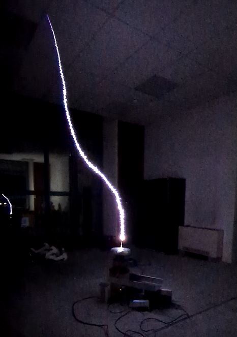
photo: one channel to the ceiling (HVF 3097) 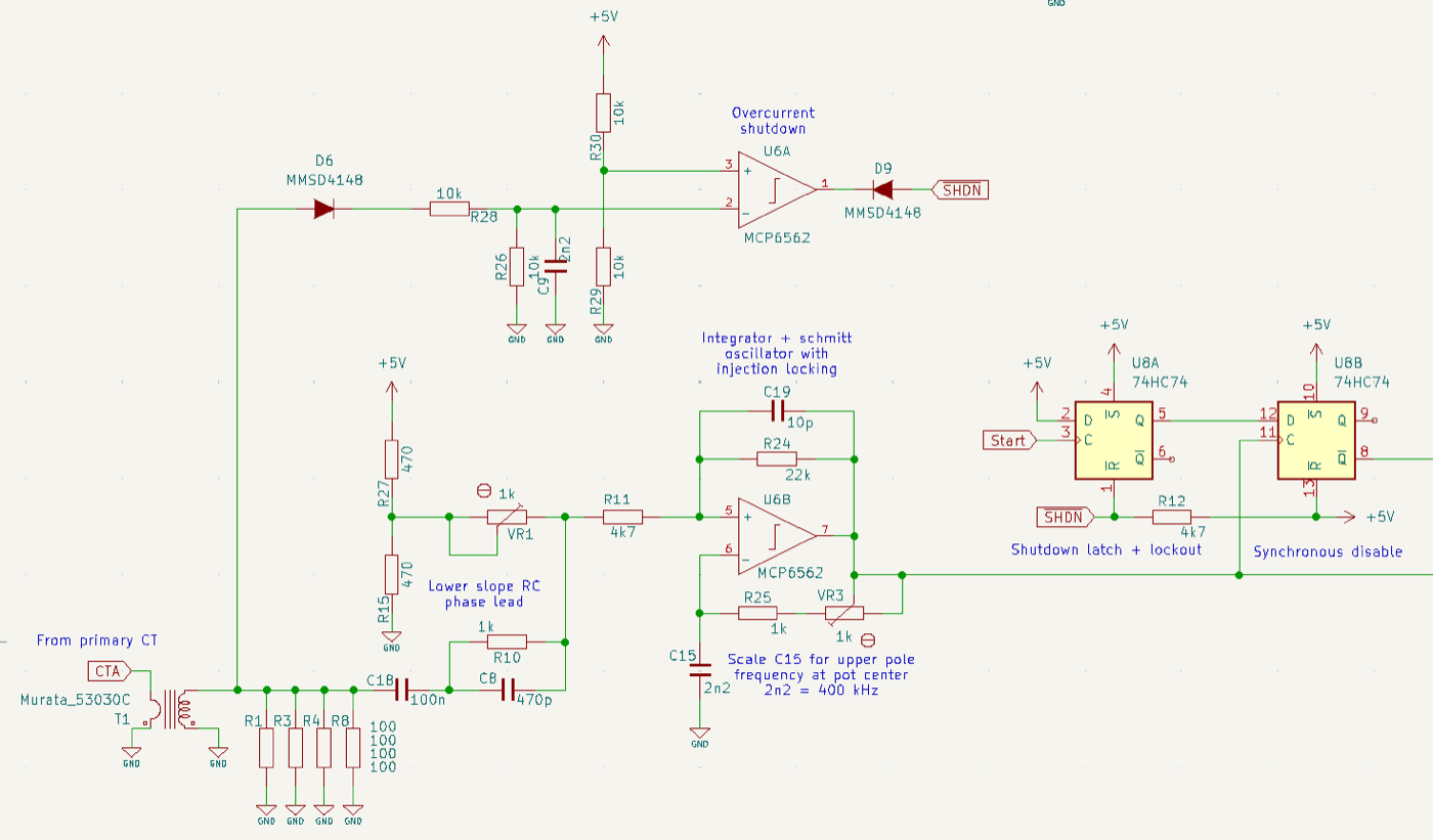
oscillator + overcurrent schematic (KiCad, 2024) 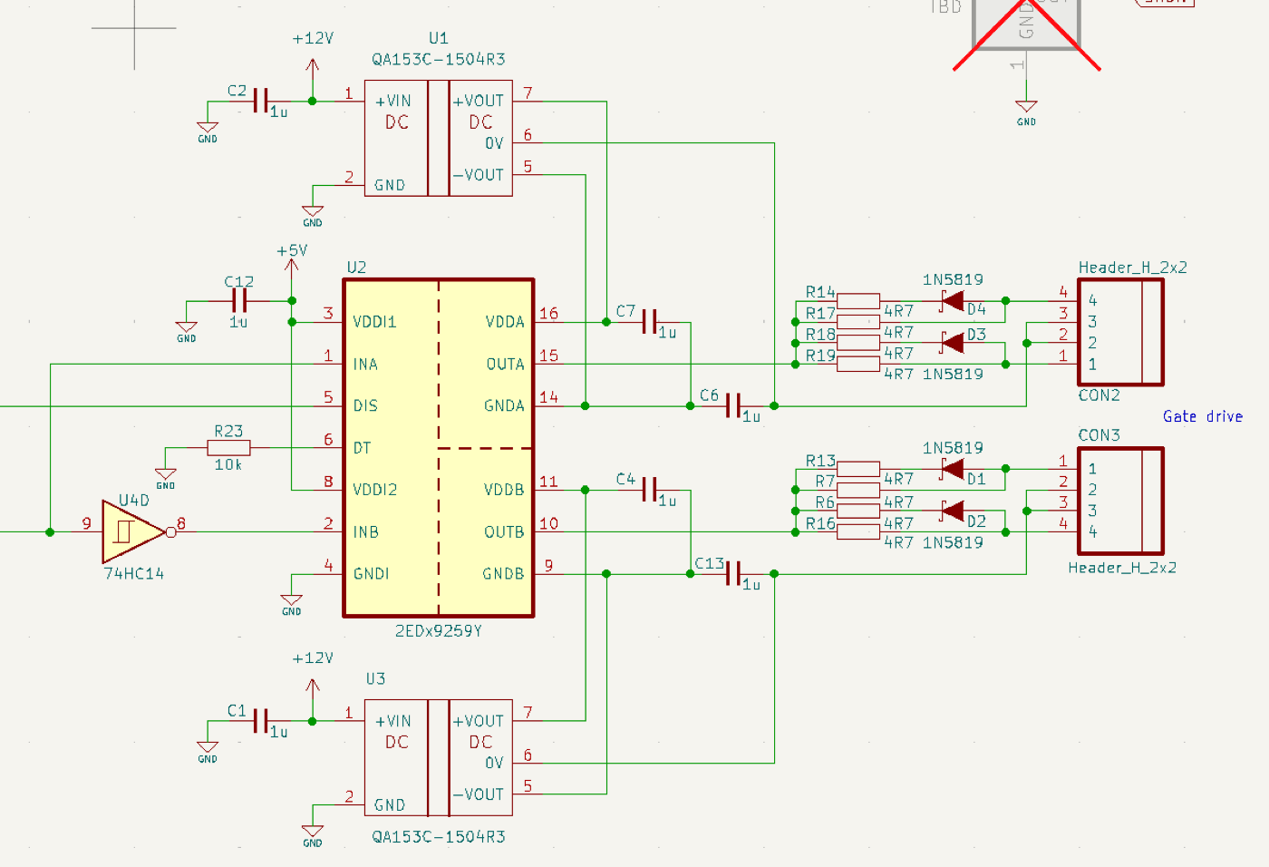
isolated gate-drive schematic (KiCad, 2024) 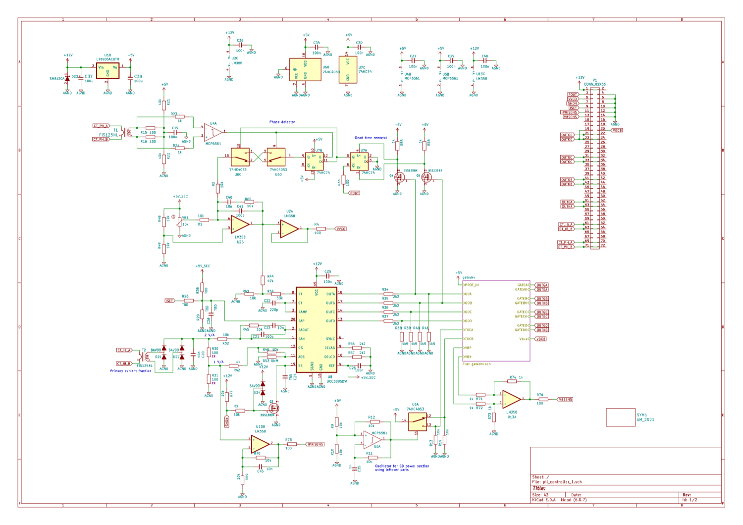
PSFB controller schematic (KiCad, 2022) 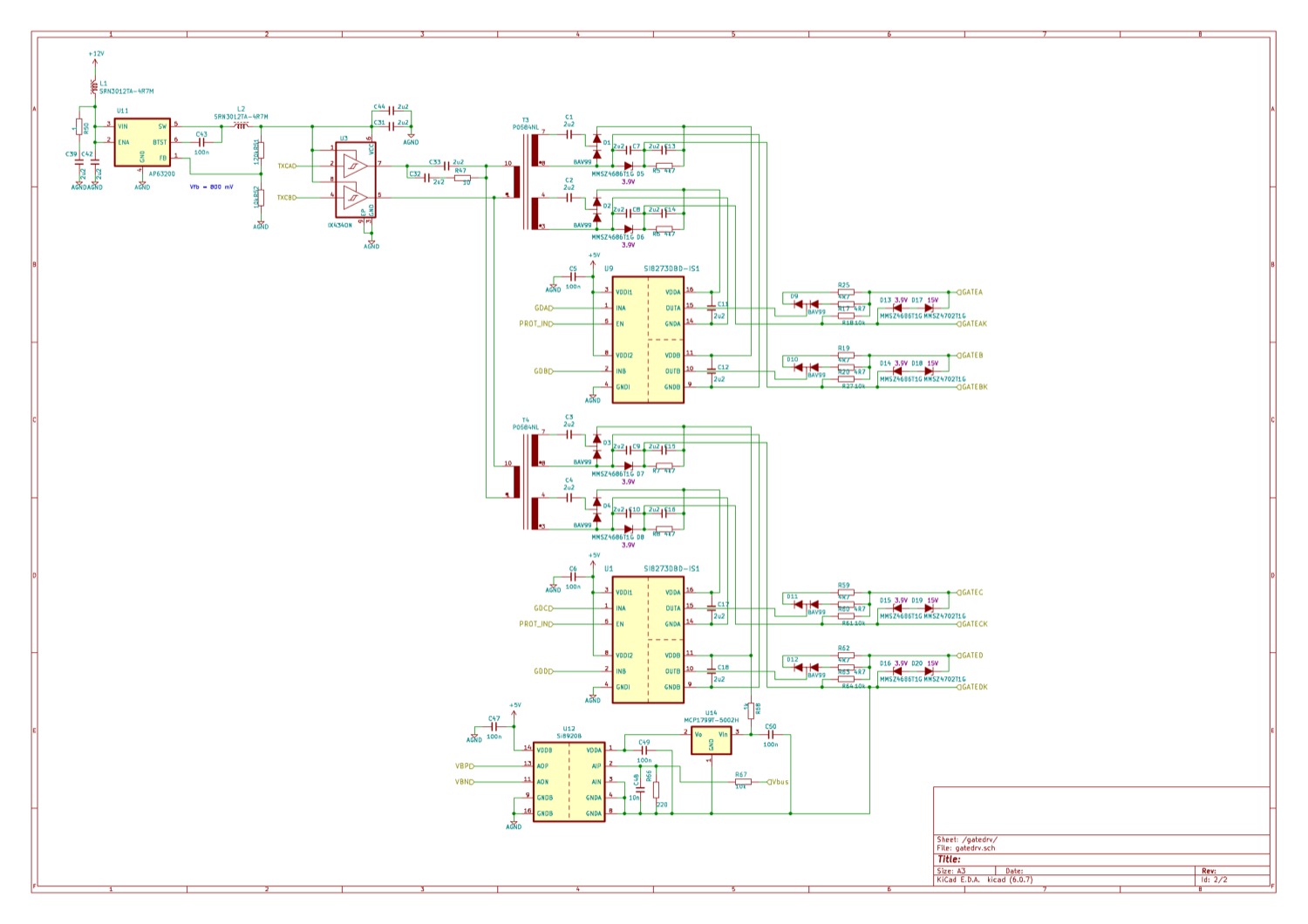
gate-drive schematic (KiCad, 2022) 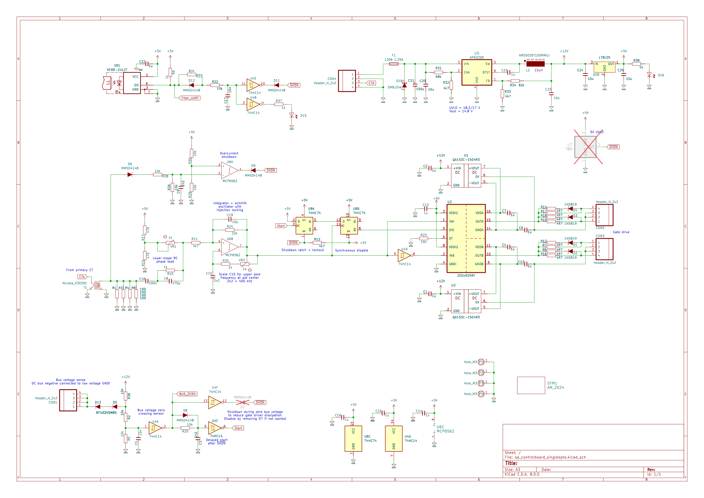
control-board schematic: qa_controlboard_singleopto (KiCad 8, Sep 2024) 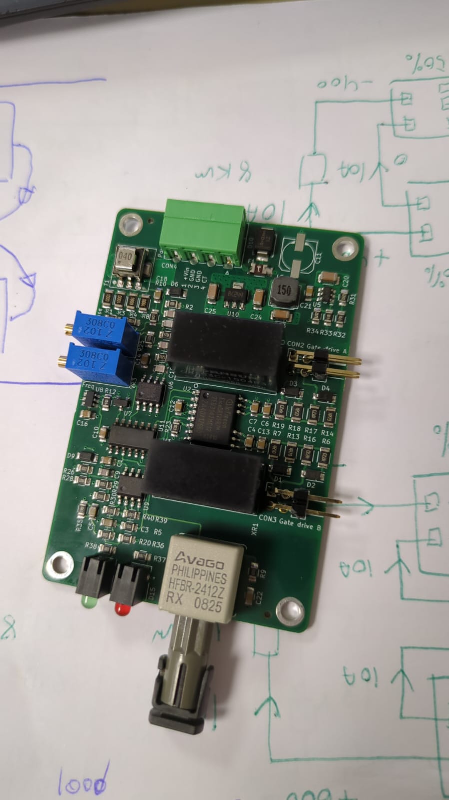
assembled control board: HFBR-2412Z fibre RX, 2EDx9259Y, isolated DC-DCs 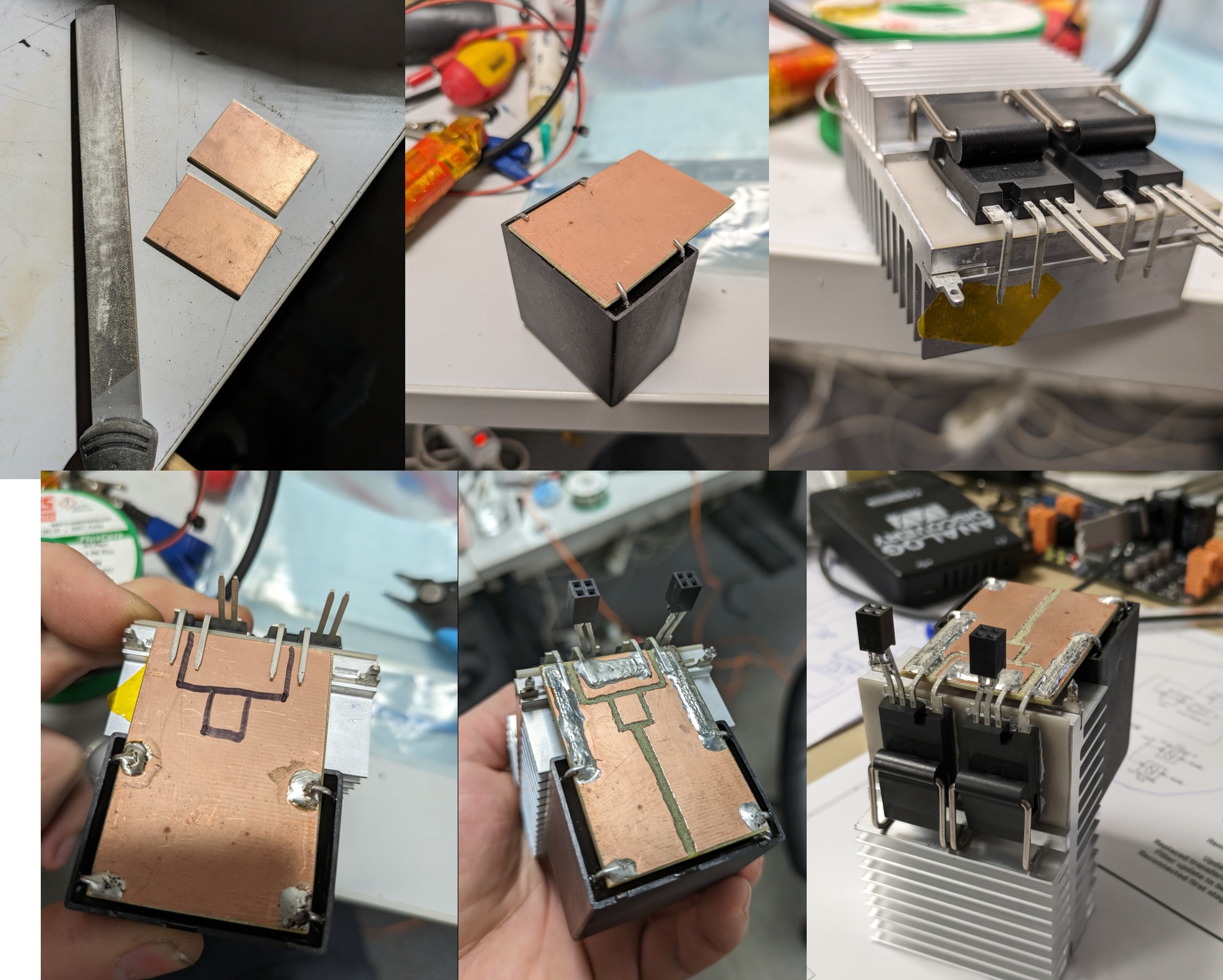
SiC half-bridge construction: copper bus plates, TO-247 on heatsink 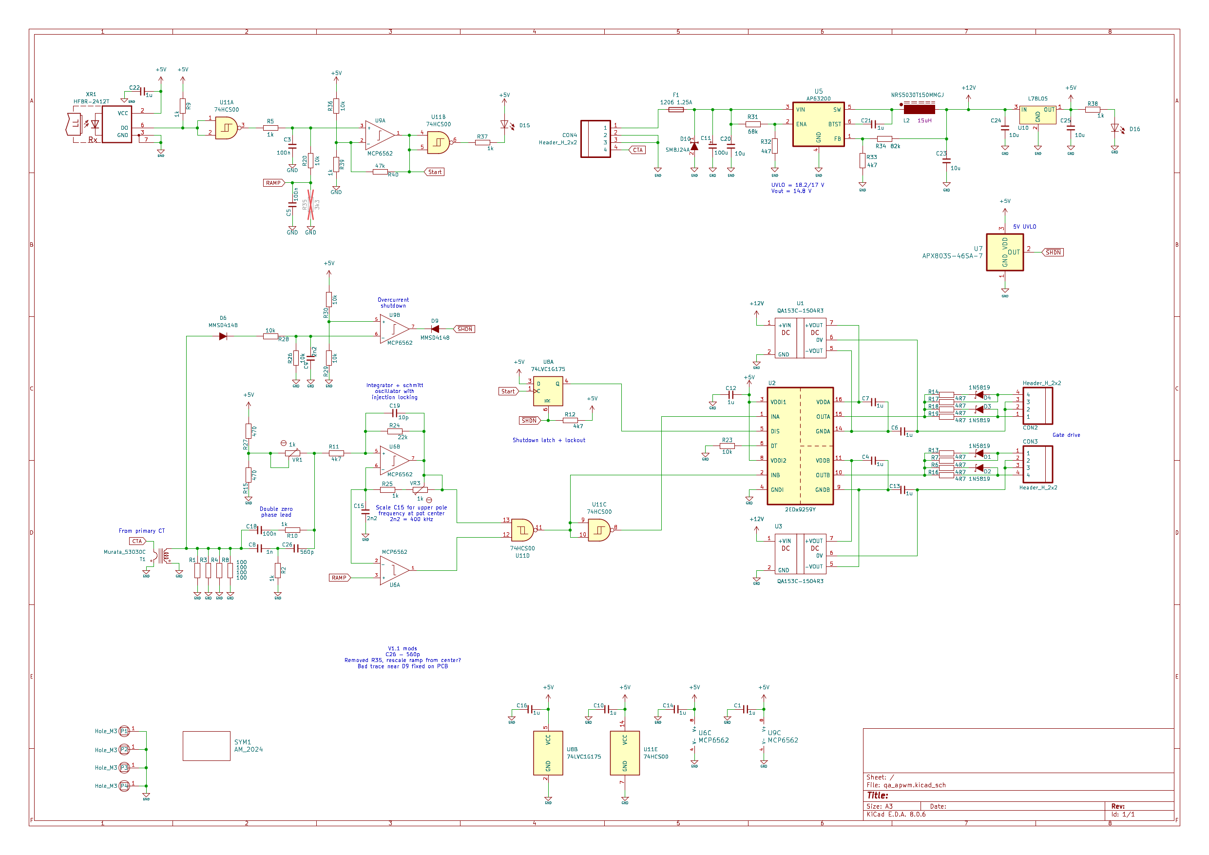
APWM driver schematic v1.1: qa_apwm (KiCad 8.0.6, Jan 2025) 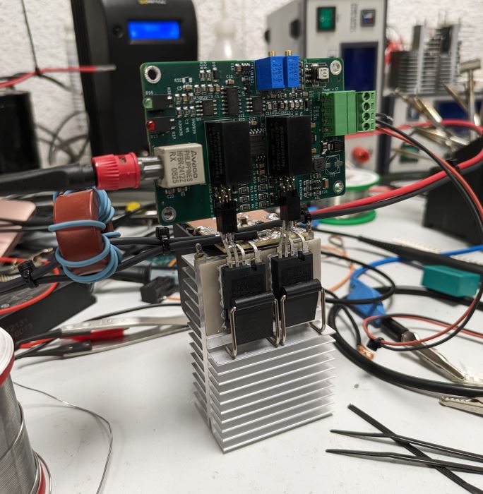
the APWM board soldered straight onto the bridge: gate pins into female headers 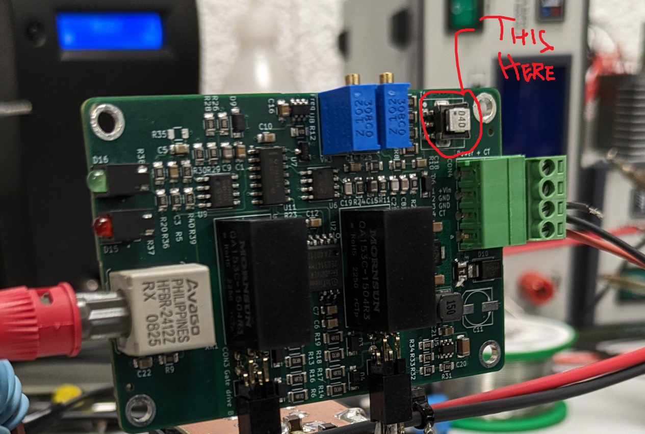
APWM control board flat: HFBR-2412Z fibre RX, two Mornsun QA153C isolated supplies, the second on-board CT he circled
Sources
- highvoltageforum.net: evolution of a solid state Tesla coil
- highvoltageforum.net: adventures in induction heating, 2015 (where it starts)
- highvoltageforum.net: PSFB induction heater, 2022 (the QCW II precursor)
- commongnd: records
This is the card from the driver tree, written from what the builder published. Send corrections through the forum.