The next thesis in the same department, under the same supervisor, three years on. It says where its control board came from: the schematic is captioned as taken and adapted from Pařenica’s. The changes are what a full bridge needs. There are two UCC27525 drivers in place of one, each with its own gate-drive transformer carrying two secondaries and switching two of the four IGBTs. The rest is recognisably the same board: the Schmitt inverters, the adjustable phase-shift network on the current-transformer feedback, the start-up oscillator, the D flip-flop that makes the 150 A limit drop whole periods, the undervoltage lockout, and the optocoupled input with its stuck-generator watchdog.
He sized the power side by calculation. It runs at 200 kHz off mains, with four FGH75T65SHDTL4 on a common heatsink sized from the loss calculation and two 560 µF 450 V electrolytics. The input has an EMC filter and a relay soft-start. Bursts are held to 100 µs and 5 % duty, a little over a kilowatt. Both boards were drawn in Eagle and made as proper PCBs. The stated aim is the longest discharge, for teaching and for visual and sound effects. Tuned on the bench, it reached the 50 to 60 cm he had aimed for. Audio modulation is discussed at length and then left to whatever generates the input pulses. He notes that the control circuits do not provide it.
Schematics and photos
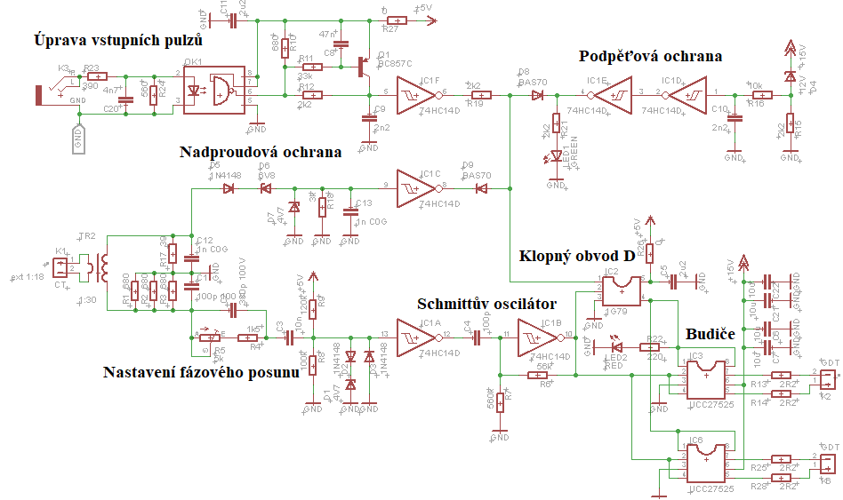
schematic: control and bridge drivers (thesis fig. 5.2), captioned there as adapted from Pařenica’s 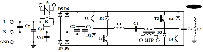
schematic: the full-bridge power stage (fig. 3.2) 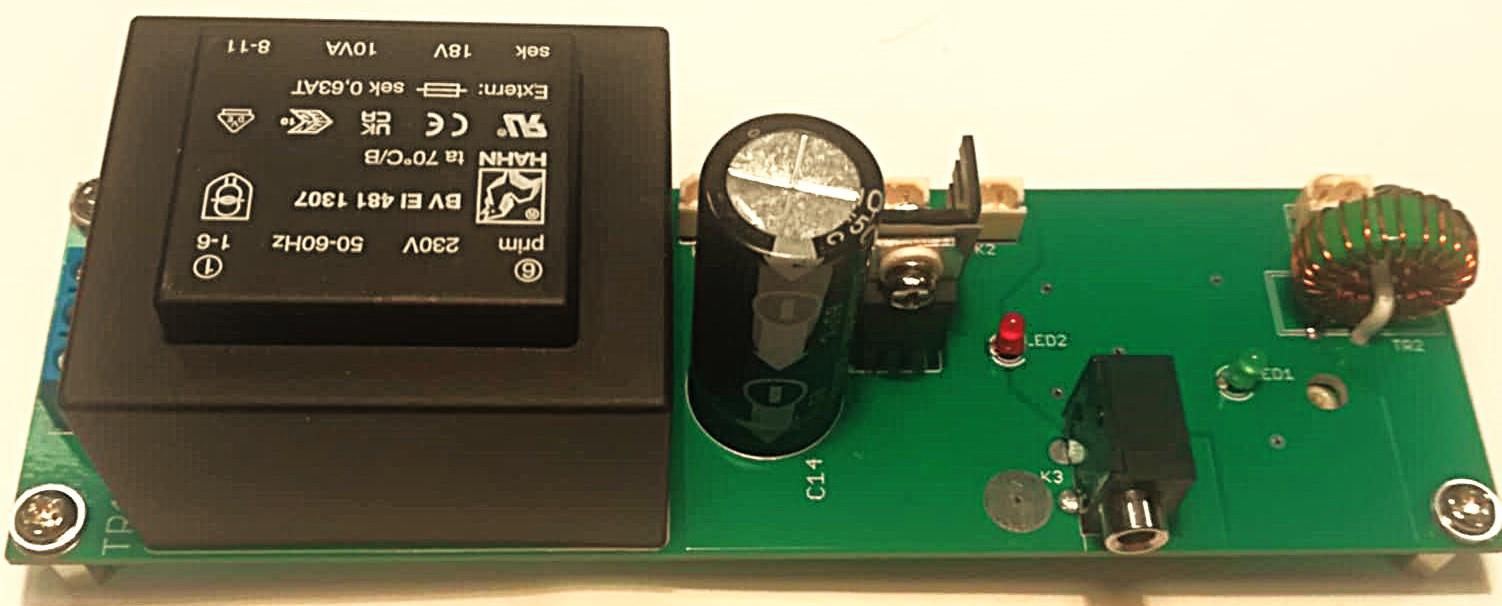
the control board, populated (top): mains transformer, regulator, input jack, on-board current transformer 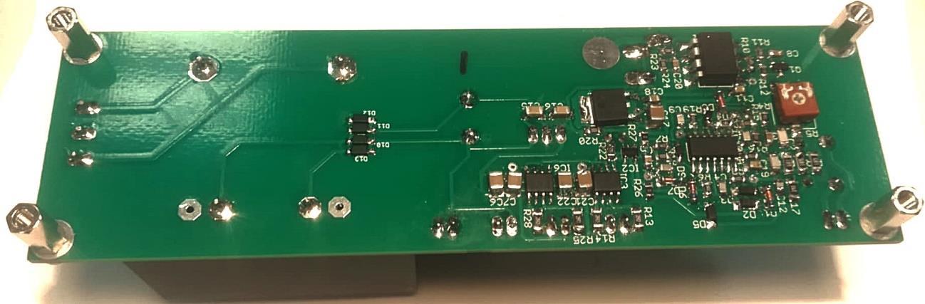
the control board: underside, with the surface-mount logic and drivers
Sources
This is the card from the driver tree, written from what the builder published. Send corrections through the forum.