A bachelor’s thesis at Brno University of Technology, Department of Power Electrical and Electronic Engineering, supervised by Jan Martiš and dated 31 May 2022. It started a small line of its own. Three years later the next thesis in the same department begins from this one’s control board. The machine is a DRSSTC run in bursts. A half bridge of two FGH75T65SHDTL4 IGBTs runs on rectified mains, with the primary returned to the midpoint of a split resonant capacitor (27.9 nF against 10.1 µH by his sizing, about 300 kHz). He says the 150 A peak was chosen from experience of running coils, because it cannot be calculated. The secondary is 1090 turns of 0.18 mm wire, 24 cm of winding on a 75 mm pipe. The power board was etched in the school lab. Tuned, the coil gave discharges of 25 to 30 cm.
The control board is the part that was reused. There is no microcontroller on it, only one 74HC14 hex Schmitt inverter, a single D flip-flop and a UCC27525 driving the gate-drive transformer. Feedback comes off the primary through two current transformers in series, 1:18 and 1:30, onto two shunts. One shunt feeds an adjustable RC network (a trimmer sets how far ahead of the current zero the bridge switches), and a clipper and a Schmitt gate square the output. A Schmitt oscillator starts the bridge before there is any current to follow, and the feedback takes over once there is. The other shunt is the current limit. Past 150 A the enable is withdrawn. The enable goes through the flip-flop, which is clocked by the feedback, so the drive is withheld for one whole period and comes back on a zero crossing, never in mid-cycle.
The board also has an undervoltage lockout on the 15 V gate supply (below it the IGBTs would be half-on and cook). The burst input is optocoupled, with a watchdog transistor that ends the burst if the outside pulse generator ever sticks high. The thesis assignment covers the power stage and its board. The control board is described block by block rather than derived, and the sheet has no title block, so the document does not say who first drew it.
Schematics and photos
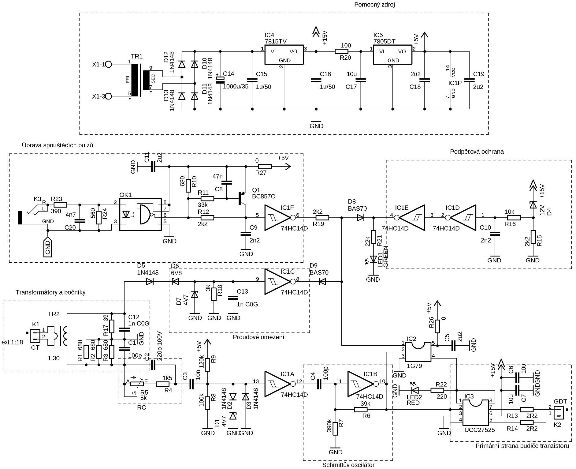
schematic: the control board (thesis fig. 2.8): CT feedback, phase-lead RC, start-up oscillator, D flip-flop, UCC27525 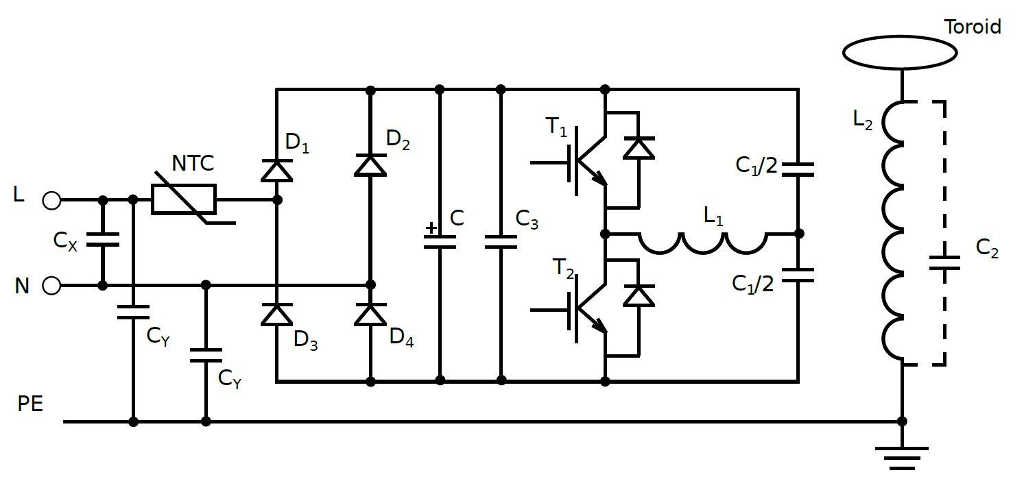
schematic: the power stage (fig. 2.1): half bridge into a split resonant capacitor 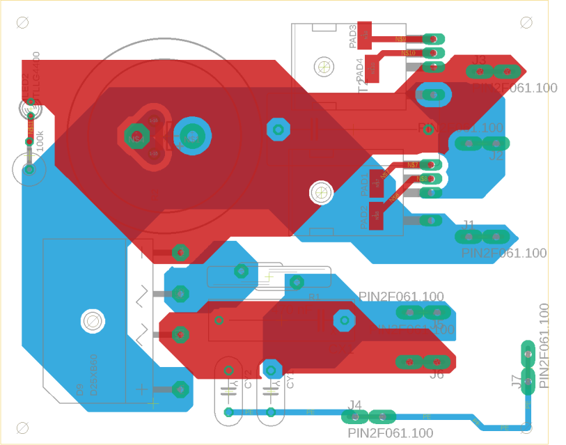
layout: the power board as drawn in Eagle (fig. 3.2)
Sources
This is the card from the driver tree, written from what the builder published. Send corrections through the forum.