“I finally got started on a Dual Resonant SSTC. This is just a little one with TO-247s, so I can get a feel for how it works before I try anything big.” The primary, secondary and tank capacitor came from his Tesla-2 spark-gap coil, and the PLL driver board from the DWSSTC. The bridge was four Fairchild HGTG30N60A4D IGBTs (600 V, 75 A, 200 ns turn-off) on a four-layer laminated bus of copper sheet and double-sided board. He tested it first into a halogen lamp through a capacitor. In part two the PLL got an interrupter, with a 4013 flip-flop snapping the end of every burst to the nearest primary current zero. Ward added the same idea to DRSSTC-1 in March 2005 with a JK flip-flop. Secondary base-current feedback was unstable under ground arcs, with up to 180 degrees of phase shift, so he went to primary current feedback through a CT cascade. Tuning for zero-current switching and tuning for maximum current did not line up until he added primary inductance, wire wound round tea mugs. About 20 in at 1 bps on 300 V. Then came a test at Alan Sharp's hall on the OLTC II supply: 1.3 A at 400 V DC, 80 bps, 36 in strikes to ground, and a blinding flash. The H bridge exploded and pieces of IGBT flew about the room, with Sharp and Burnett as witnesses. In a note of June 2006, after a 4hv member found the same oddities, he says he is not sure how good a DRSSTC driver this is and points people to Ward's instead.
Schematics and photos
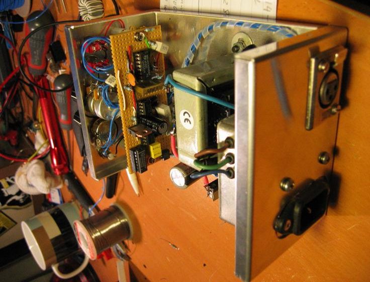
photo: the PLL driver in its shielding box 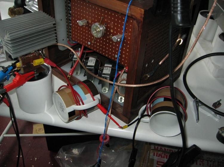
photo: extra primary inductance, wire round tea mugs 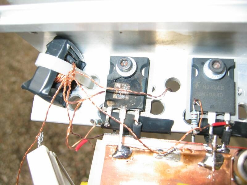
photo: the H bridge after 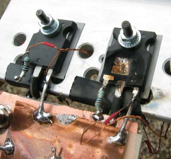
photo: what was left of the IGBTs
Sources
- scopeboy.com: The Dirty DRSSTC (pictures index)
- scopeboy.com: The Dirty DRSSTC, part 2 (archived Feb 2006)
- scopeboy.com: the great explosion
This is the card from the driver tree, written from what the builder published. Send corrections through the forum.