An undergraduate thesis in Electrical Engineering at the Universidad de Zaragoza (Escuela de Ingeniería y Arquitectura), directed by Francisco Pérez Cebolla and Jesús Letosa Fleta. It is not a fork of any driver on the tree. It was built from circuit simulation (PSpice) and field simulation (FEMM) instead of an existing Tesla-coil schematic. A full H-bridge of FGH40N60 IGBTs, borrowed from the university's Electronic Engineering department, is switched by an SG3525 PWM controller through four TLP250 optocoupler gate drives. The drive circuit was adapted from a power-electronics course exercise originally meant for MOSFETs in a resonant induction-hob converter. It was built as a flexible test bench rather than a finished display coil, and the thesis is open about the gap between paper and hardware. The first PCB came back with a missing fuse footprint, a relay installed backwards and a solder bridge with under 1 mm of clearance, all fixed by hand with a Dremel. The stock 1 µs gate dead-time had to be cut to 750 ns on the bench before the bridge would even reach the required frequency. Dielectric-breakdown tests followed. Driving exactly at either resonance peak gave 14.4-25.3 kV across the secondary capacitor by calculation. The thesis's original result is that driving slightly off resonance, at the frequency of minimum primary current, gave a wider and more reliable sparking range (9-13 mm of gap, 28.3-36.8 kV) than either resonance peak on its own.
Schematics and photos
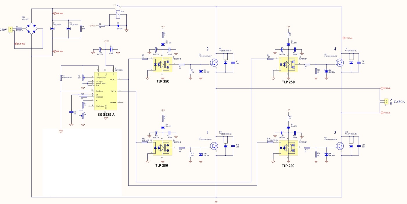
driver schematic 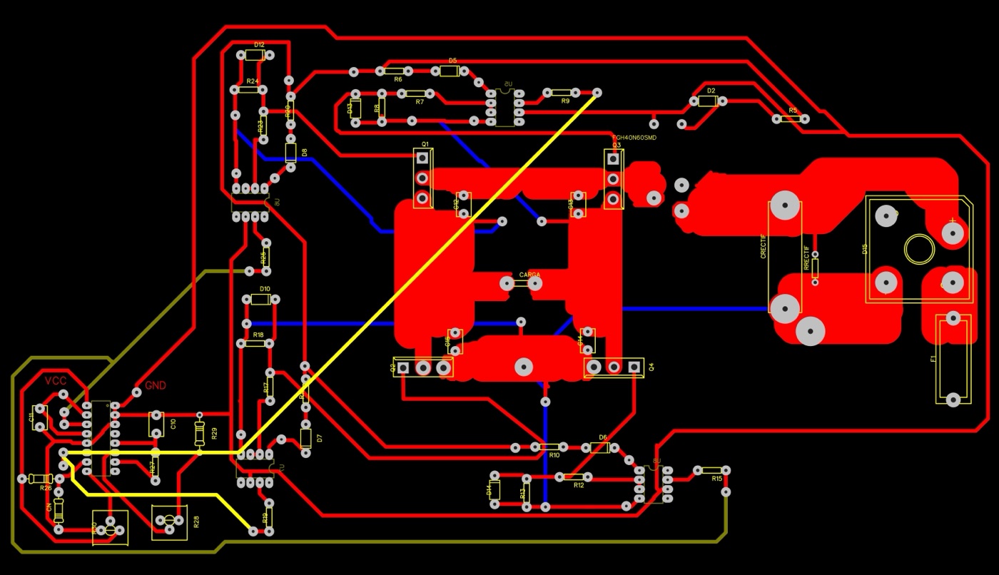
PCB layout
Sources
This is the card from the driver tree, written from what the builder published. Send corrections through the forum.