Everything sits in a PC power supply case, labelled by him: full-wave rectifier, smoothing capacitor, two 1:1 gate drive transformers, the IRF840 full bridge, the PC supply's own fan, the on/off switch and the two interrupter pots on the lid, feedback in on one side and the primary out on the other. The driver board close up shows TC4429 drivers, the CD4001 drive logic, the CD4046 preparing the feedback signal and the LM555 interrupter. The schematic has four blocks (interruptor, feedback, drive logic, gate drive) and a note that a higher-frequency coil wants the logic on 5 V and 74HC parts. It is antenna feedback, always in tune, seven months before the same idea became the root of this lineage in Ward's hands.
Schematics and photos
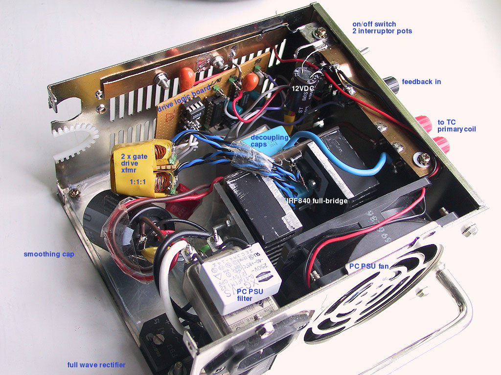
photo: the driver in its PC supply case, annotated 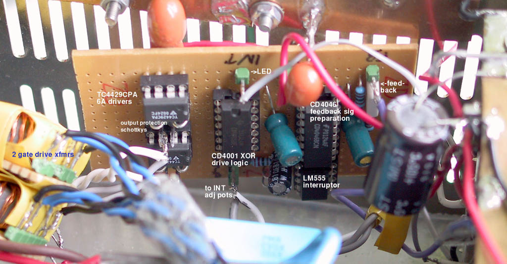
photo: the driver board, annotated 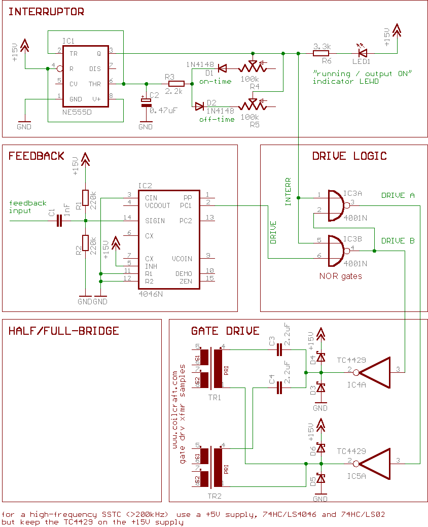
schematic: interruptor, feedback, drive logic, gate drive
Sources
This is the card from the driver tree, written from what the builder published. Send corrections through the forum.