The bench photograph, labelled by him: the bucket secondary, a 320 V DC supply behind a mains isolation transformer, the UC3846 driver section, the gate drive, the interrupter on its own 12 V. The bridge section was rebuilt as a mk 2 for a much better RF layout, with local decoupling on the back of the board and the ultrafast diodes in the middle. Archived by June 2002.
Schematics and photos
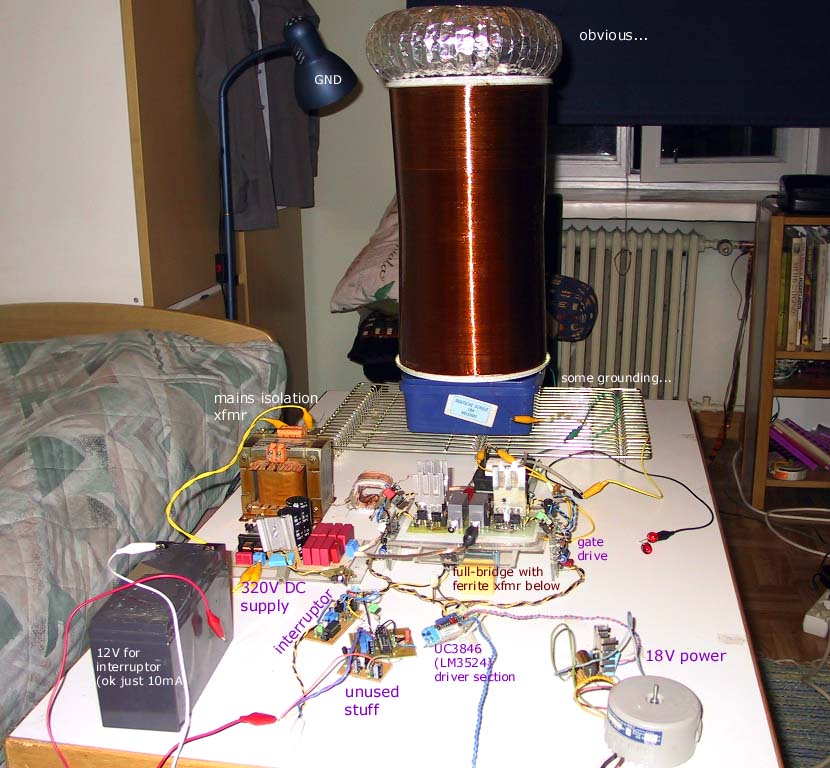
photo: the bench, annotated by its builder 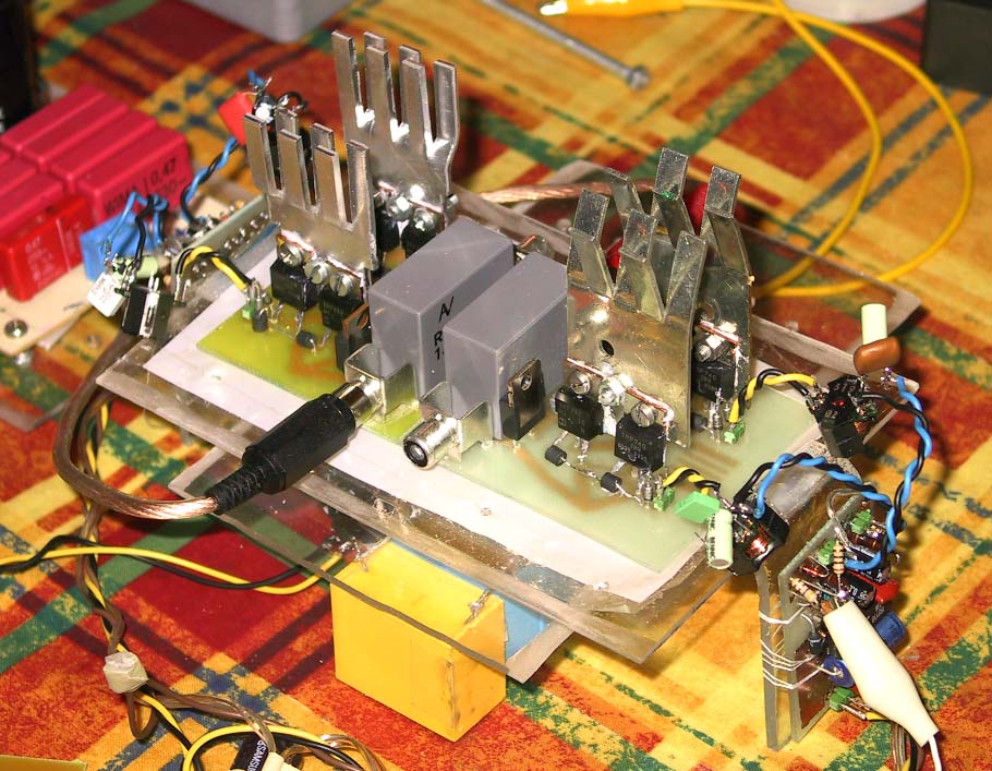
photo: the first full-bridge section on its plate 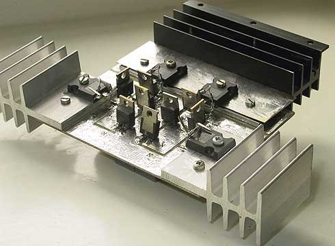
photo: the mk 2 bridge section
Sources
This is the card from the driver tree, written from what the builder published. Send corrections through the forum.