A from-scratch design. Cordingley built it after finding both ElectroBOOM's SSTC (no secondary feedback) and the OneTesla kit (feedback-less, relying on a close-enough primary LC tune) lacking. His driver locks to the secondary's actual resonant frequency through a PLL and drives the primary continuously ("it seems accurate to me to call it a continuous wave type driver") instead of bursting like a DRSSTC. He sets out the case for SiC himself. Ordinary DRSSTC-style IGBTs switch fine under 200 kHz, but a continuous-wave half bridge has to run at the secondary's own resonant frequency, 300 kHz-1 MHz, and that needs MOSFET-class speed. He chose Cree (now Wolfspeed) C3M SiC MOSFETs for their IGBT-like voltage handling with low gate charge and low RDS(on). The design is split across three stacked boards. A mains-direct power supply rectifies straight to ±170 VDC rails with no transformer. An audio/control board carries the PLL, a frequency-dependent ramp generator (a BJT current source fed by the PLL's own VCO voltage) and filtered secondary feedback. The driver board has an ADUM4120 isolated gate driver ahead of the SiC FET. The two boards talk over CAN bus, chosen for its EMI immunity around a running coil. All four schematic sheets (power, two audio sheets, driver) are published at full resolution.
Three years later he published the hardware for the next revision, which carries the same idea forward: “these are the hardware source files for my 2022 revision of my musical solid-state Tesla coil driver. **This is a completely analog design. No firmware!**” There are eight board folders (control board, full-bridge driver, PFC power supply, power switcher, switch board, audio isolator), each with its KiCad schematic and layout, gerbers, and a STEP model of the assembly. The control board’s block diagram draws the chain the 2019 write-up described in words. Secondary feedback goes through clamp diodes into gain and filtering, then a PLL, an edge-triggered one-shot, the ramp generator, and a PWM modulator that the audio path feeds from the side. A CAN-bus link goes out to the full-bridge driver. The ramp generator sheet itself has 58 parts (ADA4891-2 op-amps, a 74HC86 marked “Edge Detect”, an MMBT3906 current source and two trimmers), with nets named FREQ_IN, RAMP and RST_PULSE. No licence is stated on the repository.
Schematics and photos
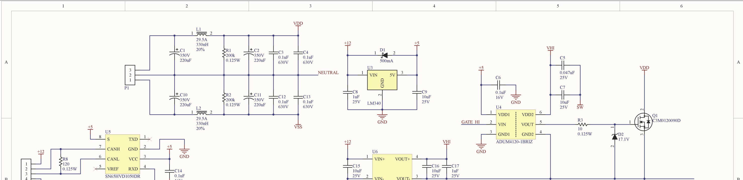
driver schematic (SiC half bridge) 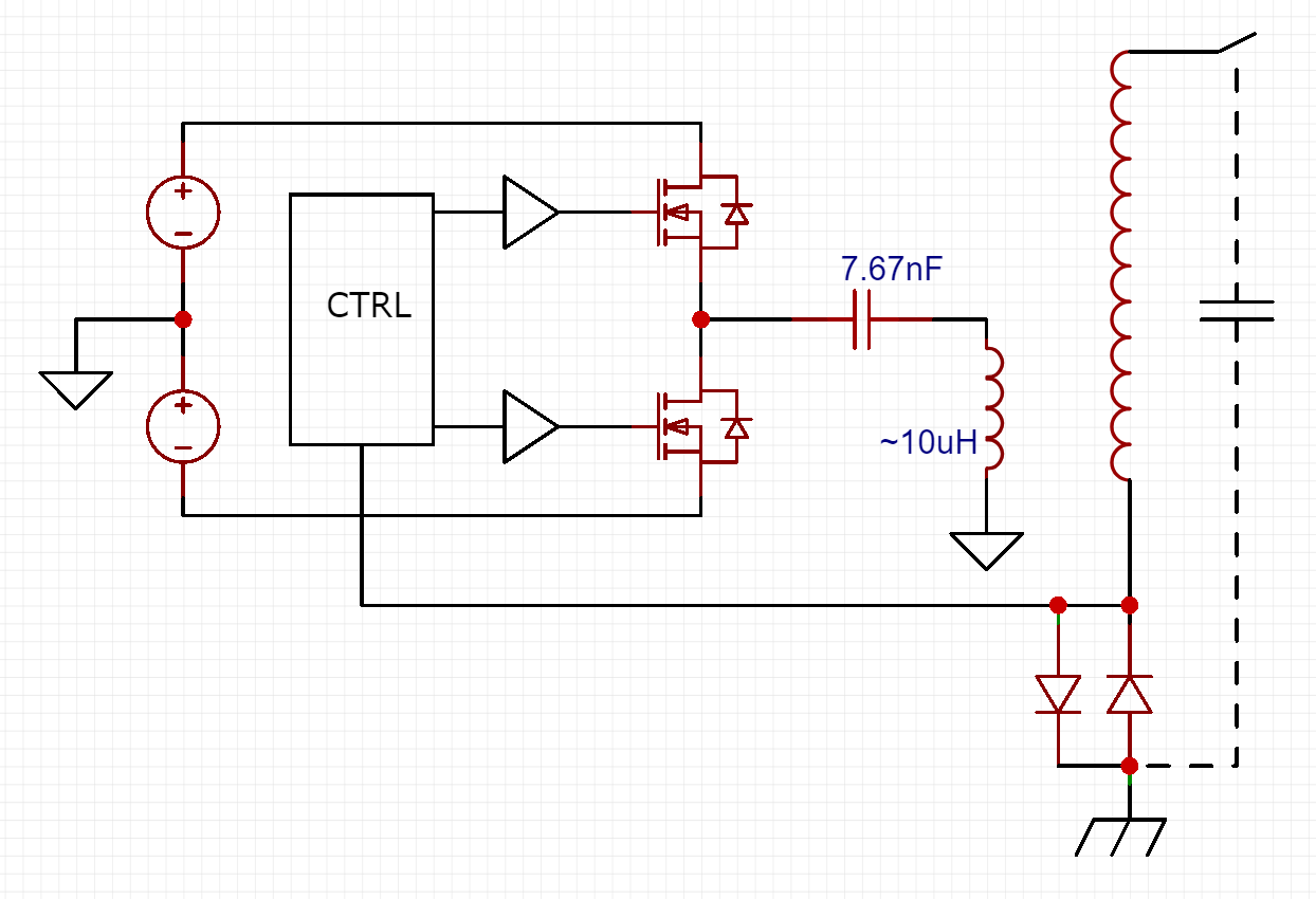
conceptual schematic (coupling-capacitor explanation) 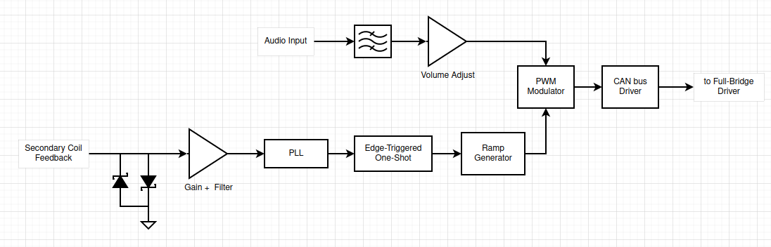
control-board block diagram: feedback → PLL → one-shot → ramp generator → PWM → CAN 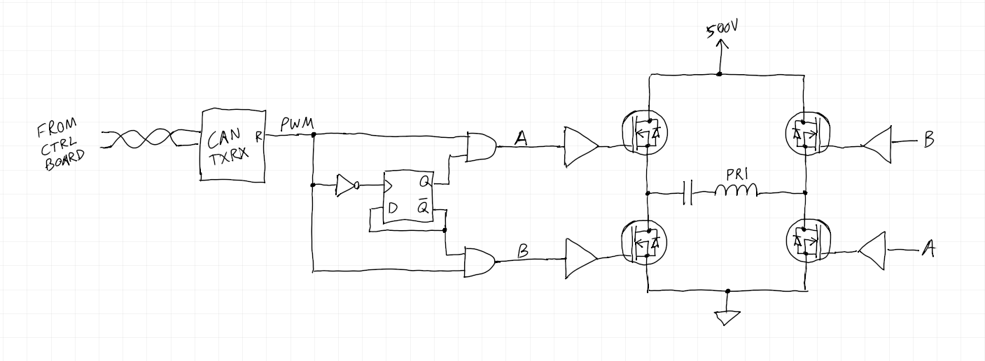
his own hand-drawn explanation of the full bridge, CAN receiver to the four switches
Sources
- acordingley.us: Tesla Coil
- github.com/AdamC19/Musical_SSTC_Driver, the 2022 revision: KiCad sources, gerbers and STEP models for all boards
This is the card from the driver tree, written from what the builder published. Send corrections through the forum.