A QCW ramp got by leaving the modulator out altogether. Zach Armstrong, who posts as LabCoatz, published it on 17 February 2022 as “building the world’s simplest QCW DRSSTC”. The sheet states its ancestry along the bottom edge: “Designs based on the Loneoceans RSSTC, modified by Zach Armstrong of ‘LabCoatz’ and Ryan of ‘Magneticitist’.” So it is a modification of Gao Guangyan’s RSSTC by two named people, not an independent invention. It is placed here as a fourth way of making the ramp because it fits none of the three technique nodes.
The author explains it on the drawing: “This staccato interrupter is what allows the circuit to create a ramped input without a complex buck converter. It reads the AC signal from the 12V transformer and turns on the circuit in sync with the rising AC sine wave.” Two NE555s do it. One sets pulse width on a 20 kΩ pot and the other the rate on a 100 kΩ pot, each fired through a 2N2222 off the rectified line. The ramp is the mains half-cycle itself, so the bus needs neither a buck stage nor a large modulator capacitor.
The rest is a conventional dual-resonant chain, with the reasoning written on the sheet. Antenna feedback at J1 (“may be substituted with a feedback transformer”) goes into a 74HC14, then a 74HCT74N flip-flop which the sheet says “helps ensure the IGBTs soft-switch, which is necessary for dual resonant operation”. That feeds a UCC37321 and a UCC37322 driving a gate-drive transformer of 8 turns to 12 + 12 on 25 mm ferrite (#77 or #75). The bridge is two FGA60N65SMD IGBTs with 5.6 Ω gate resistors, protected by “two 1.5KE220CA in series for each IGBT”. It has an 80-100 nF film MMC, 0.68 µF/500 V bus caps and a rectifier rated “over 500V/15A, over 100A peak”. Secondary: between 300 and 600 kHz. His own is 3.5 in by 5 in of 34 AWG at 350 kHz under a 6.5 in toroid.
Published openly and in full: Gerbers, a parts list with purchase links and a 15-page instruction document. The document properties name Zach Armstrong as its author and date it 26 March 2022. No licence of any kind is stated anywhere in it. Nikki Cooper made a second, cleaner KiCad redraw in December 2024 and documented the errata between the original sheet and the shipped PCB. R20 and R21 are missing from the original drawing but present on the latest board, R10 and R11 are swapped, and R11 is drawn as 2 kΩ where the silkscreen says 2k2. No photograph of an assembled board turned up. The forum posts carry the schematic, the PCB artwork and the instructions, and every image on the author’s own project page is of the discharge.
Schematics and photos
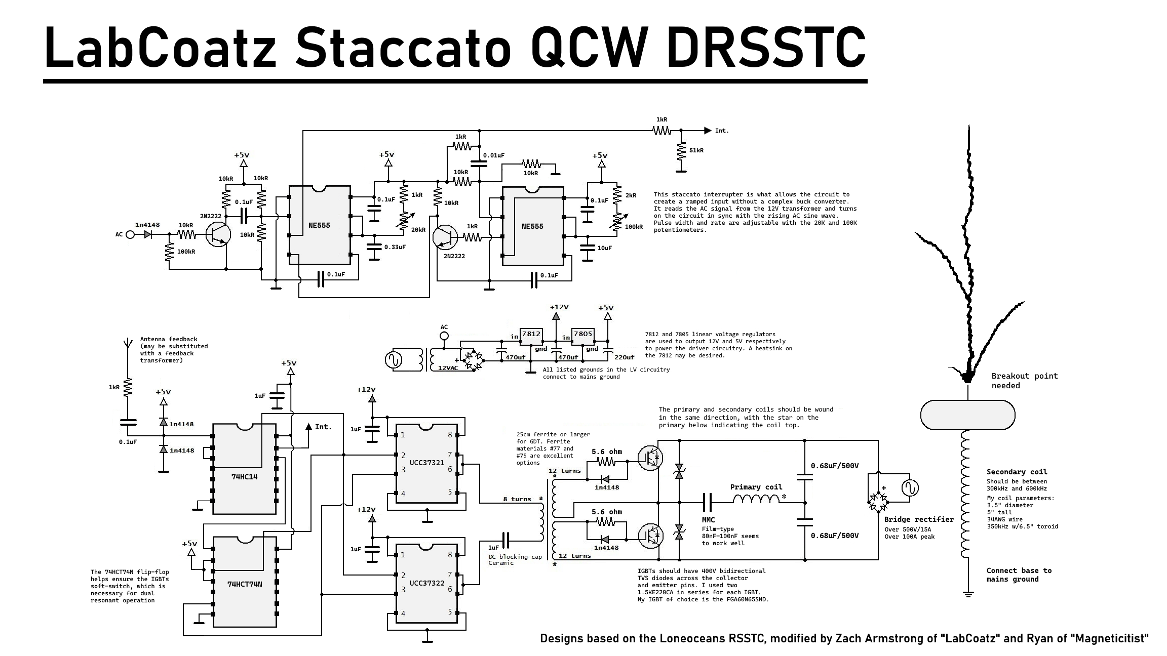
schematic: “LabCoatz Staccato QCW DRSSTC”, the author’s own sheet
Sources
- hackaday.io: Building the World’s Simplest QCW DRSSTC (Zach Armstrong)
- highvoltageforum.net: the author’s schematic, PCB artwork and instructions
- highvoltageforum.net: Nikki Cooper’s KiCad redraw and errata notes (2024)
This is the card from the driver tree, written from what the builder published. Send corrections through the forum.