A ramp generator in a microcontroller instead of analog hardware, and the earliest of the ramp boards in the tree. Finn Hammer put it on the forum on 26 November 2019: “From time to time, I have been approached with a request to share my QCW ramp generator code. Everybody should be enabled to build a QCW coil, even though they cannot write code, so here it is.”
He released an archive of exactly two files, the sketch and an Eagle 6.5 sheet called “QCW generator hookup”. The sheet is small: an Arduino Pro Mini, five trimmer pots, two switches, four resistors, two capacitors and a pair of 1N4148s. Two labels on the drawing show where the signals leave: “to pulse fiberled” and “to PWM fiberled”. The ramp goes out as filtered PWM on one fibre and the burst trigger on the other. The code names the pots AMPLITUDE, PULSELENGTH, SCALE, BPS and WICK. WICK is a short low shelf held before the ramp starts to rise. The first line of the sketch states the job: “Generates the ramp signal, that serves as control reference to the QCW Buck converter.”
Asked how coarse the result was, he measured it: eight bits at 32 kHz on the ATmega328P, and nine bits at 160 kHz with the same code loaded into a Due. Rafft, already on the records wall in this branch, built it two years later and said so: “Huge thanks for the Interrupter + ramp!” He posted a trace and noted it was the filtered PWM output, not the buck. Hammer also appears in the DRSSTC lineage, for the 2009 phase-lead gate driver he called the Predikter.
Schematics and photos
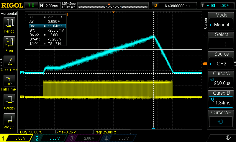
his own scope capture of the 12.8 ms ramp
Sources
This is the card from the driver tree, written from what the builder published. Send corrections through the forum.