A German build documented on his own site, well past the numbered-driver line. It is a full H-bridge of four IGBTs rated 800 A continuous, 1600 A pulse, at 1200 V, off rectified three-phase mains near 560 VDC. His own logic board (v1.6) handles the resonant-frequency feedback. There are four separate half-bridge gate-driver boards, fibre-optic (TOSLink) isolation between logic and bridge, and an AtMega128-based remote control unit. The page names Ward's UD1.3b as one influence on the logic, but the current and voltage ratings and the board layout are his own. By his own account this was the earlier project: "I began this project long before the Minitesla, but could not complete it for various reasons". A much smaller SSTC on the same site got finished first, while the three-phase H-bridge waited. It uses an NE555 oscillator into UCC37321/37322 gate drivers and a pair of IRFP460 MOSFETs, with the signal carried across on a trifilar-wound ferrite ring, priced against Reichelt's Nov 2008 catalogue. The page has full schematics for the whole chain: main power stage (rectifier, bus cap, H-bridge, GDT and feedback transformers), the v1.6 logic board (74HC14/74HC08/74HC74 logic plus a CA3140 comparator reading the feedback and OCD transformers), the IGBT driver stage, a power-on timer and the remote control. That makes five separate circuit diagrams. We missed them on the first pass through his site and found them on a second, closer look.
Schematics and photos
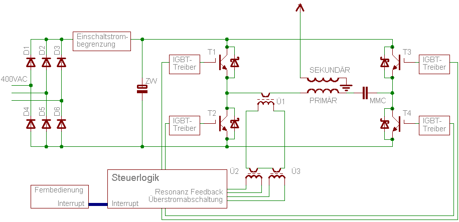
main power-stage schematic (Stromlaufplan) 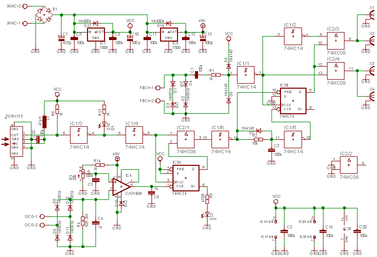
logic board v1.6 schematic
Sources
This is the card from the driver tree, written from what the builder published. Send corrections through the forum.