This board sits between controller and bridge. It takes logic-level drive and turns it into gate current through a hand-wound transformer. Hydron is already named on this tree (the UVLO idea on the UD2.0/2.1/2.5 card is credited to him). This is a design of his own, published under the MIT licence with the full Altium project, gerbers, BOM and reference outputs.
Each channel is a dual driver IC on 12 V feeding complementary DMC3021LK4-13 MOSFET pairs running from 24 V. Every totem pole has a 1 kΩ and MCL4148 bootstrap pair and local 10 µF + 0.1 µF decoupling. The outputs leave through 1 nF snubbers and a 15 Ω / 1 µF / 2.2 µF network to the gate-drive transformer. There are two channels to a board (“two off for full bridge setup, 4 for dual full-bridge”). A second board can be slaved to the first over an expansion connector, and a separate SLAVE output variant is generated for that.
The README lists the problems plainly. It opens with a warning that creepage between the bridge voltages and the low-voltage side is only 1 mm, so nothing connected, including the controller on the RJ45, may be touched with mains applied. It notes that the regulator on the “12 V” net is actually a 5 V part, and that the three 1000 µF capacitors are oversized for ordinary non-QCW use. The gate-drive transformer is to be wound by hand. He describes the intent: RG-174 coax with the shield as primary and the centre conductor as secondary, for high coupling.
The title block is blank (no title, no revision, no draughtsman). Only the file name GateDriver.SchDoc and the date 16 January 2017 are left. There is also no photograph of a built board, by his own statement: “will supply pictures once I have built the PCB and wound the transformers.” The card shows the schematic only.
Schematics and photos
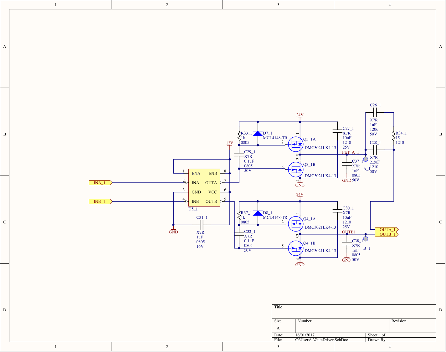
schematic: one gate-drive channel (Altium, 16 Jan 2017, title block blank)
Sources
This is the card from the driver tree, written from what the builder published. Send corrections through the forum.