A minimal-parts trick. The same two gate-drive transformers that run the bridge in normal operation, 180° out of phase, are driven back *in phase* with each other for active freewheeling. That puts 0 V across the primary tank, and current recirculates through the IGBTs rather than the catch diodes, with no extra hardware just for freewheeling. A state machine switches between the two modes on the feedback signal’s rising edge, gated by over-current detection or the interrupter going low. UCC27425 gate driver, TL3116 for feedback sensing, LM311 for OCD. Fewer parts than “reference designs like the UD2.7c,” by design. Posted as a schematic on 7 Jul 2026 and revised the next day. No board has been built yet.
Schematics and photos
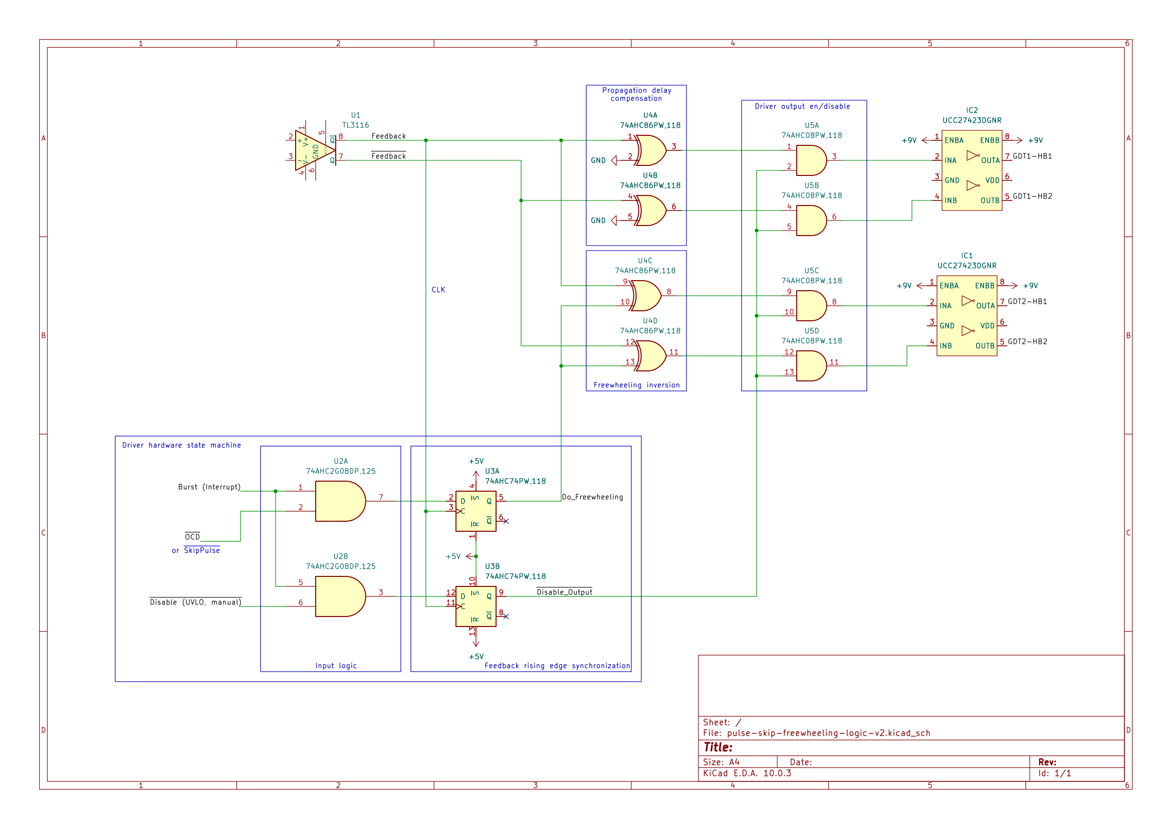
KiCad schematic: pulse-skip + freewheeling logic v2
Sources
This is the card from the driver tree, written from what the builder published. Send corrections through the forum.