His first DRSSTC followed Ward's own schematic closely. The second was deliberately miniaturised: two small PCBs stacked on standoffs, the control board at the bottom with a DB9 connector and status LEDs, and the power board above it carrying the IGBT half-bridge and its heatsinks. His one addition was an experimental comparator fed a ramp signal in place of the plain interrupter pulse. He was trying for the ramped, “sword-like” sparks that QCW coils later made into a technique of their own. By his own account it didn't work out and he abandoned the modification. He wrote up the negative result anyway, on a compact board.
Schematics and photos
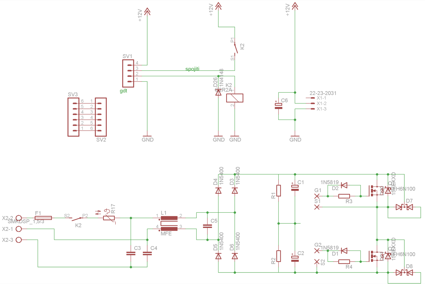
power-stage schematic
Sources
This is the card from the driver tree, written from what the builder published. Send corrections through the forum.