- #1
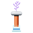
Hi! I'm a 16-year-old student in Pakistan building a Tesla coil demonstration for my school science exhibition. My target design is a single-MOSFET IRFP260N circuit, and I'm considering a 36V DC supply.
I already have some components, including MOSFETs, capacitors, resistors, a fan, and a heatsink. I'm a beginner at circuit wiring and need help checking the schematic, component values, and compatibility before powering it on.
Could someone experienced with Tesla coils or Slayer Exciter circuits please help review my circuit and guide me? My exhibition deadline is very close. Thank you!
- #2
Hi Muhammad, welcome!
36 V with a single IRFP260N can work, but I'd put a gate driver chip in front of the MOSFET. Its gate is big, about 4 nF, and these coils run at hundreds of kHz up to around 1 MHz, so in a plain slayer the coil itself has to charge and empty that gate every cycle. A driver chip does it hard and fast, so the MOSFET switches cleanly instead of sitting half-on and heating up.
I drew the circuit I'd build, it's in the picture. It's ElectroBOOM's high-power slayer (https://www.electroboom.com/?p=521) set up for 36 V. Steve Ward's Micro SSTC (https://www.stevehv.4hv.org/SSTC6.htm) is nearly the same thing at about 30 V, one MOSFET and one TC4420, so it's a proven idea.
Everything runs off your one 36 V supply. The primary and the MOSFET get the full 36 V. The only part that can't take it is the driver chip, which is rated 18 V, and the gate itself is 20 V max. So a small buck module makes 12 V for the driver out of the same 36 V. A 7812 won't do here, its input is only rated to 35 V. A normal LM2596 board is fine with a 36 V adapter, it takes up to 40 V. If you're using batteries, get an LM2596HV board, because a charged 36 V pack is around 42 V, and check that the board itself is rated for that.
Here's how it's wired. The primary is 3 turns of thick wire around the bottom of the secondary, from +36 V to the drain, and the source goes to ground. The bottom of the secondary goes straight to the driver input (MIC4452, a TC4452 or TC4420 works too, it just has to be a non-inverting one). On that input there's a 22k to +12 V, which turns the MOSFET on when you switch on, like the resistor in the basic slayer does. There are also two Schottky diodes, 1N5819, one from ground with the stripe towards the input and one to +12 V with the stripe towards +12 V. They keep the coil from pushing the input below ground or above 12 V. ElectroBOOM used a 1N4148 there, but the Schottkys drop less and take more current, which the chip's input likes better. The driver output goes to the gate through 2 or 2.2 ohm. On the driver's supply the datasheet asks for a 1 uF film cap and two 100 nF ceramics, one right across pins 1 and 4 and one across pins 8 and 5. Then 2200 uF 63 V across the 36 V close to the MOSFET, and a 3 A fuse in the + wire. Ward also has a 1 nF cap straight across the MOSFET, drain to source, rated 2 kV. I'd copy that, 1 kV is plenty at 36 V.
When the MOSFET switches off, its drain jumps well above the supply, several times higher depending on the coil. Your IRFP260N is rated 200 V, so at 36 V there's some room. Ward used an IRFP460, which is 500 V, so if you can get one easily it gives more margin. If an IRFP260N dies, that's the swap to make. Your heatsink and fan will help either way.
If you haven't wound the coil yet, Ward's numbers are a good start: a 7.5 in (19 cm) winding of 28 AWG (0.32 mm) wire on a 3.5 in (9 cm) pipe, a primary of 3 turns on a 4.5 in (11.5 cm) pipe, no top load, just a sharp wire sticking up at the top. He got sparks of 1 to 1.5 in (2.5 to 4 cm).
The first few times, only run it for a couple of seconds and then feel the heatsink. If nothing happens, swap the two primary wires, Ward's notes say exactly that. If it still doesn't start, check which way the diodes point.
Could you post your own schematic and a photo of the coil too (diameter, height, number of turns, wire size)? Then we can go through it before you switch on.
And please be careful with it. Don't run it straight from the mains, don't touch the top while it's on (RF burns hurt even from small sparks), keep phones and laptops away, air the room because it makes ozone, and have a teacher around when you test.
For the exhibition, holding a fluorescent tube near it and watching it light up with no wires always gets people. Good luck, and post photos when it runs!