What changed because of them
His 2024 coil throws arcs consistently above three metres, the longest recorded at 318 cm, off a 16.4 cm winding. That ratio is among the highest on the records wall. The driver behind it is his own: a self-oscillating comparator design with injection-locked phase lead read off the primary current transformer, overcurrent shutdown, a synchronous-disable latch, an isolated half-bridge gate drive and a bus zero-crossing sensor that times the start and stop. Every schematic is his own KiCad work, posted with the build.
He is the person who explained APWM to the forum: run the top and bottom switches of a half bridge at different, complementary duty cycles, and the drive ramps with no buck converter and no full bridge. His surprise was that zero-voltage switching survives it, as long as the phase lead rises slightly as the duty cycle falls. The modulator turned out to be almost free, a single comparison against the ramp already present in the oscillator.
The work started in 2015 as an induction heater: an IGBT full bridge with a 4046 PLL and pulse-skip power control. SiC arrived a year later, once he was building SiC converters professionally, and by 2022 it had become a phase-shift full bridge around a UCC3895. That architecture is what his next project, QCW II, scales up: SiC power modules, a three-phase front end, around 150 kW average in a burst. As of September 2026 it is design and measurement, no board yet.
He is an administrator of highvoltageforum.net and answers in other people's threads as often as his own.
Their boards
Anders Mikkelsen 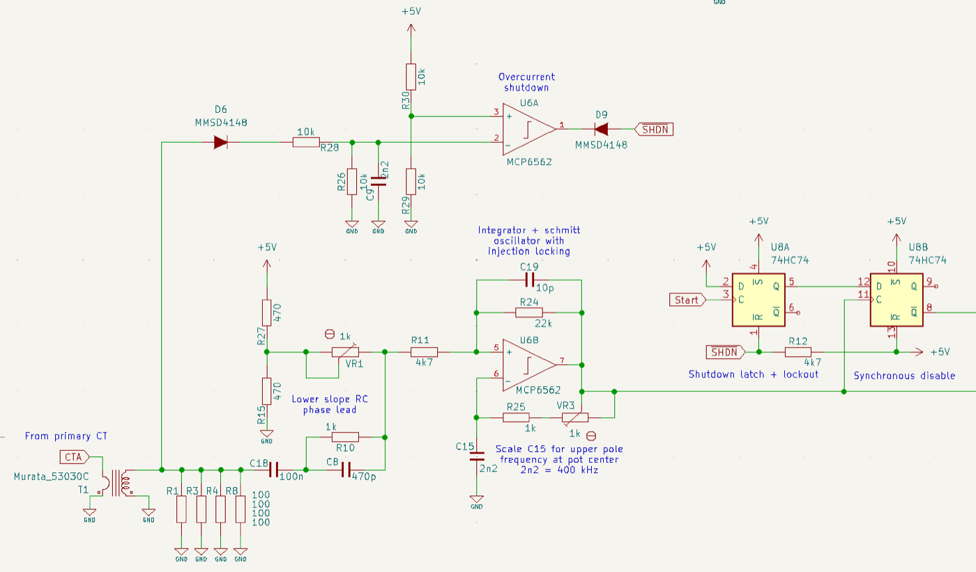
oscillator + overcurrent schematic (KiCad, 2024) 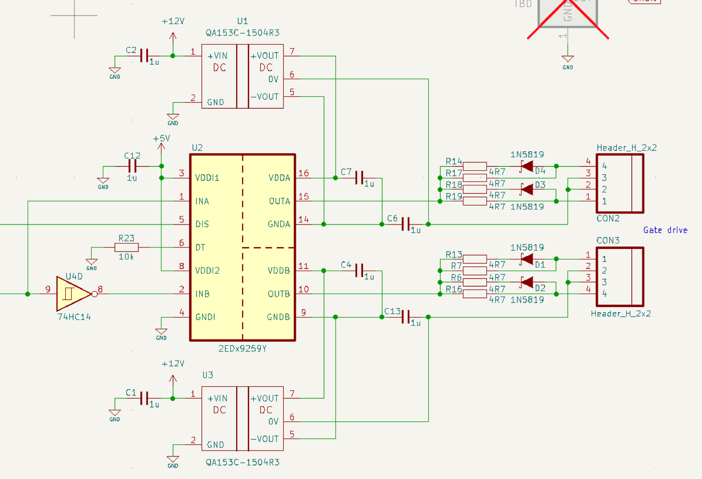
isolated gate-drive schematic (KiCad, 2024) 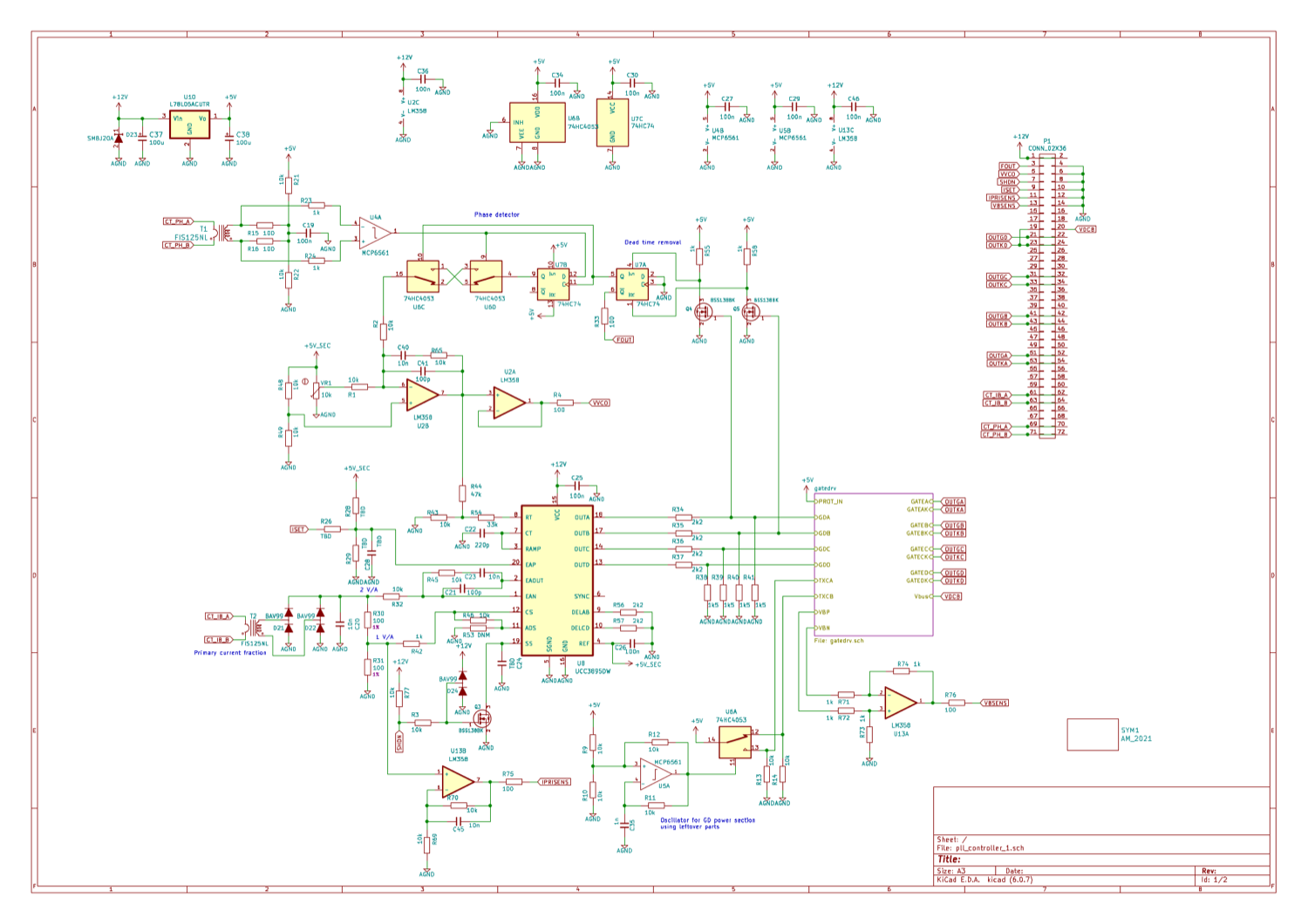
PSFB controller schematic (KiCad, 2022) 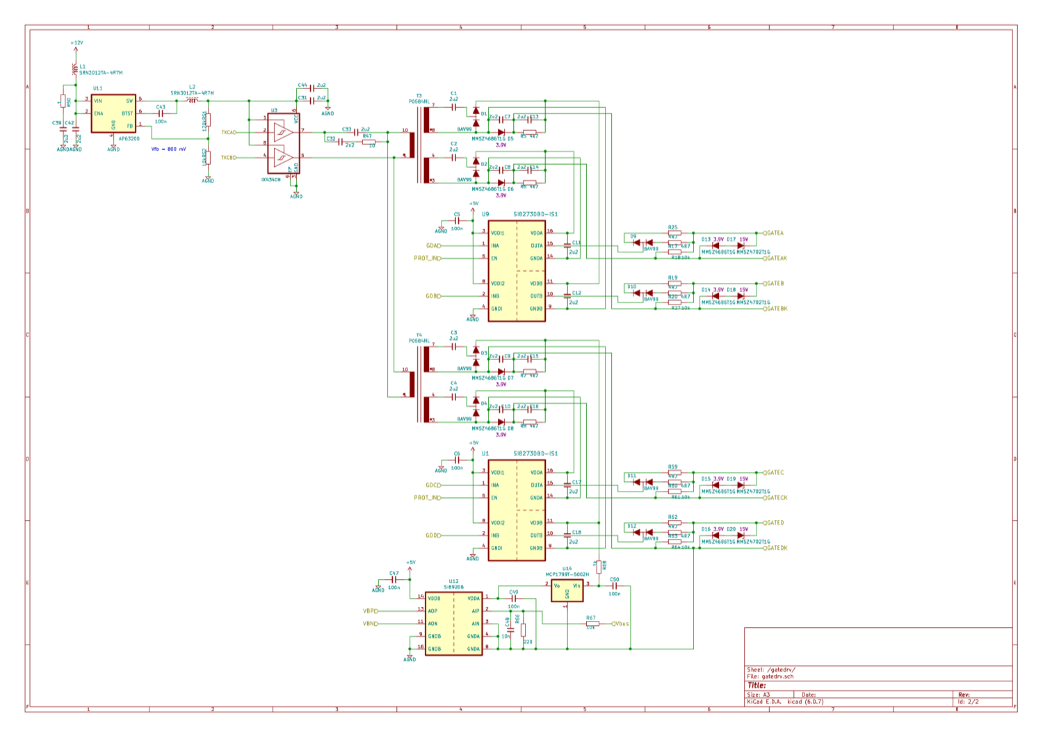
gate-drive schematic (KiCad, 2022) 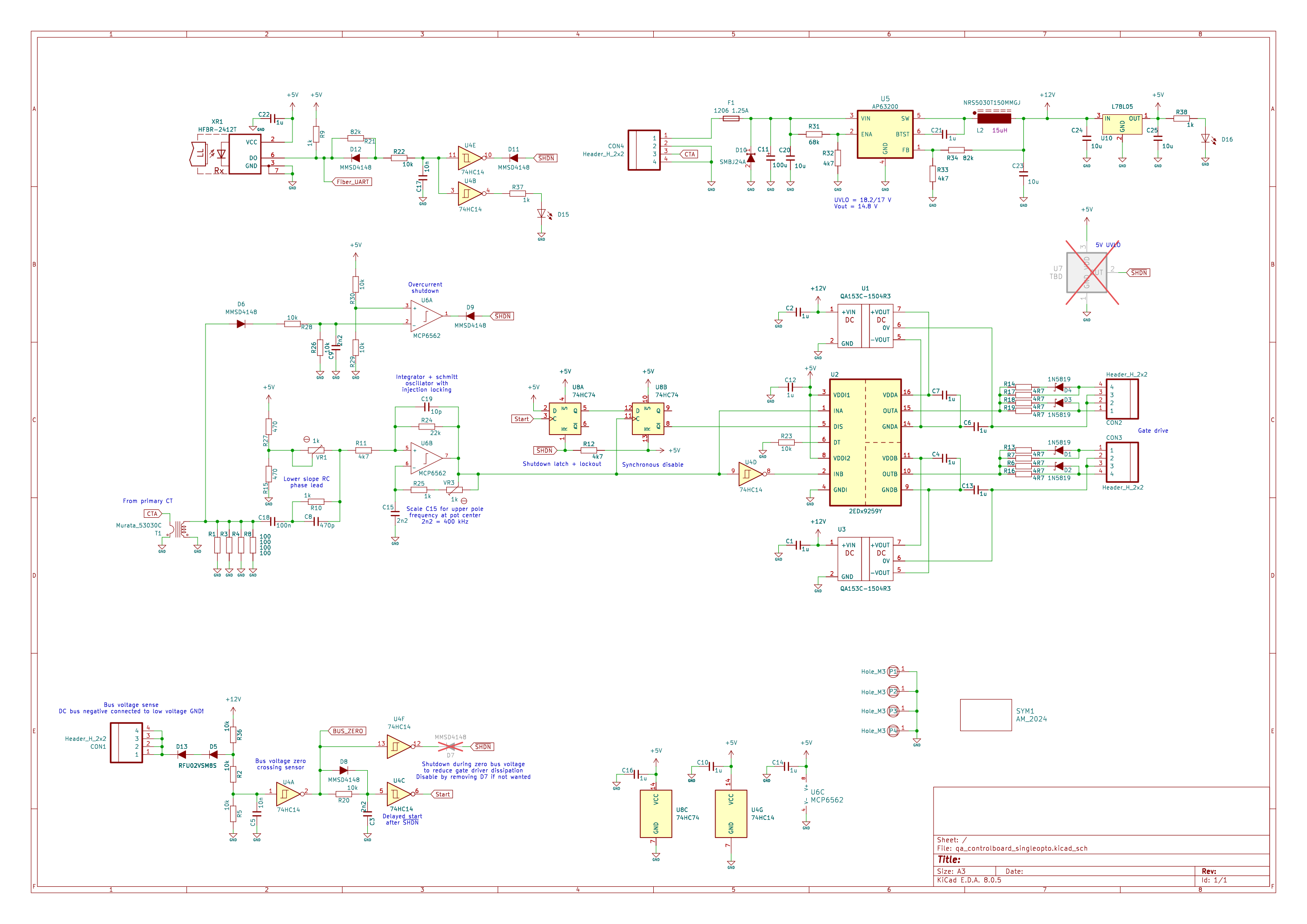
control-board schematic: qa_controlboard_singleopto (KiCad 8, Sep 2024) 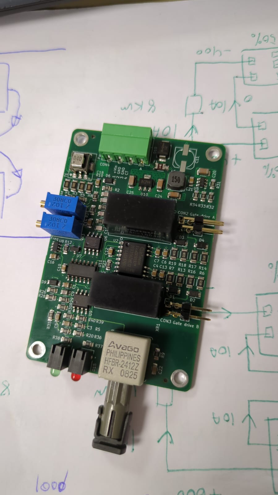
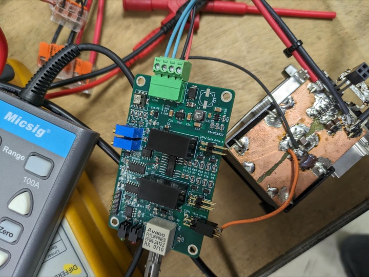
assembled control board: HFBR-2412Z fibre RX, 2EDx9259Y, isolated DC-DCs 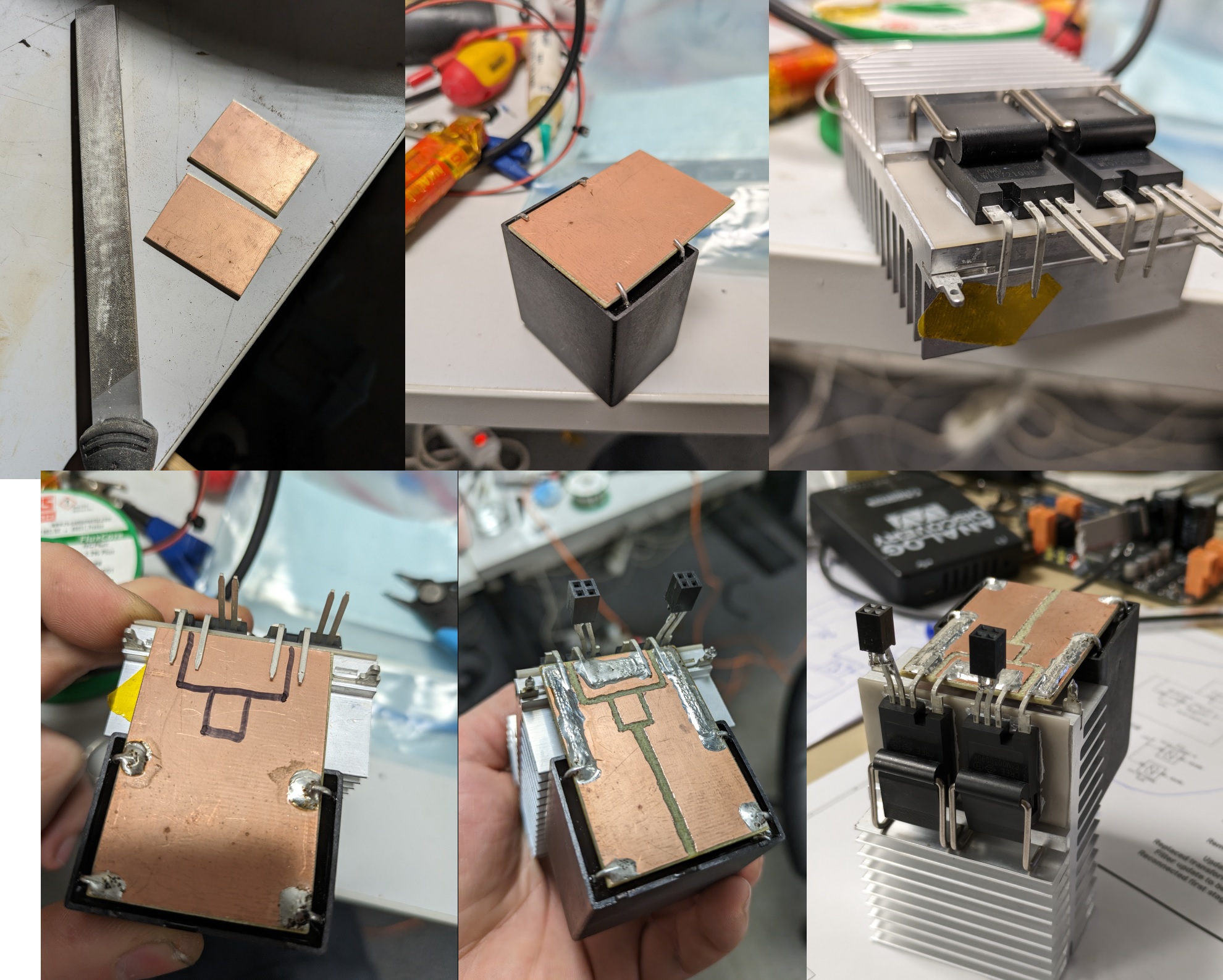
SiC half-bridge construction: copper bus plates, TO-247 on heatsink 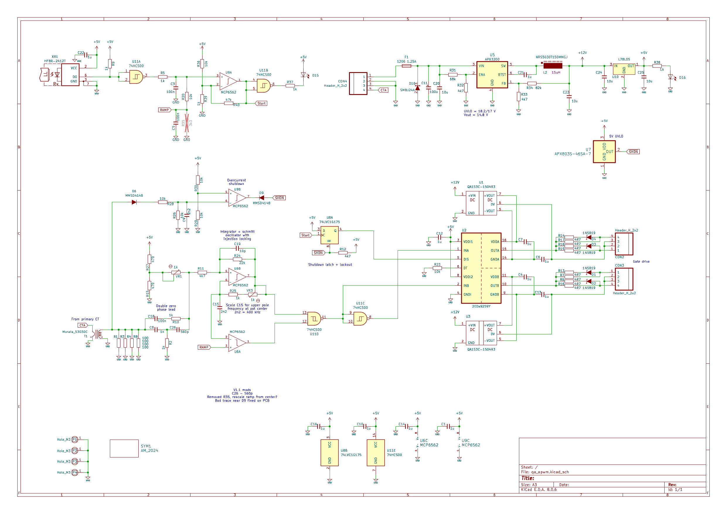
APWM driver schematic v1.1: qa_apwm (KiCad 8.0.6, Jan 2025) 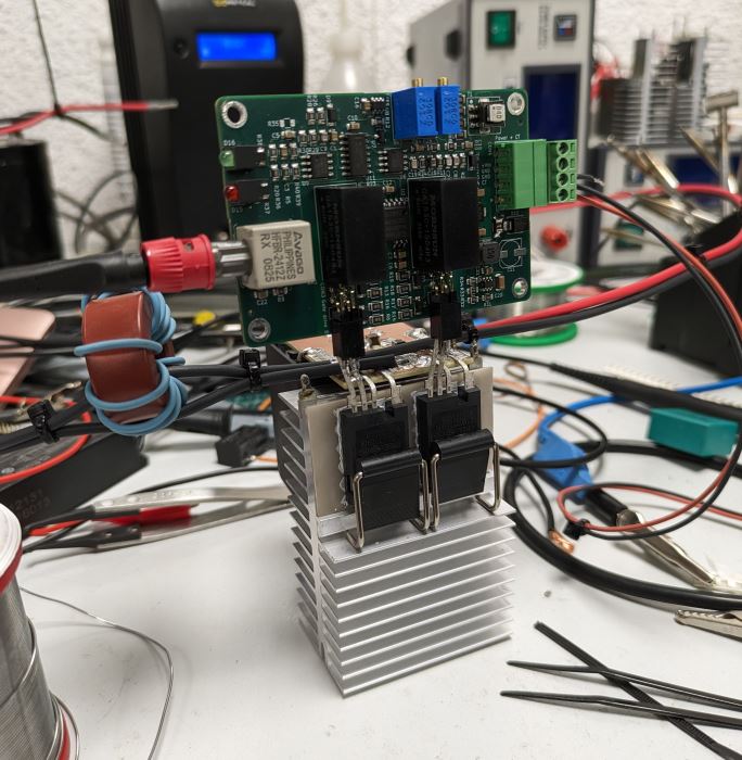
the APWM board soldered straight onto the bridge, gate pins into female headers 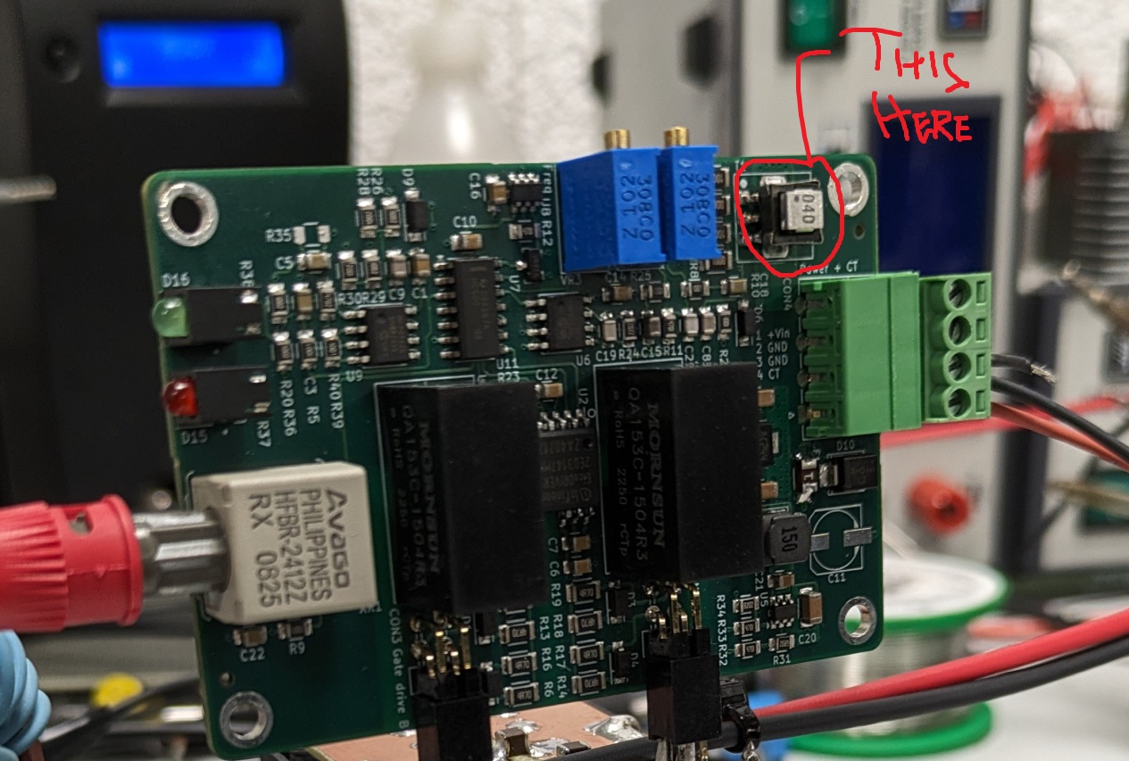
APWM control board flat: HFBR-2412Z fibre RX, two Mornsun QA153C isolated supplies, the second on-board CT he circled
Builds and boards on the tree
- SiC half-bridge QCW, 318 cm off 16.4 cm · 2024
- Ramp by phase shift and APWM · 2024
- QCW II, Beyond Reason · 2025, in design
Sources
- highvoltageforum.net: evolution of a solid state Tesla coil
- highvoltageforum.net: adventures in induction heating (2015)
- highvoltageforum.net: QCW II
Written from what Anders Mikkelsen published, by one person, so it can be wrong in places. The page is meant to become editable, wiki-style, by profiles above a trust level. Until then, corrections go to the forum, and anything Anders Mikkelsen asks to change or remove is changed the same day.