His own page for it was archived on 4 Oct 1999 and puts a safety lecture first. The coil is a magnifier of about 1500 turns of 0.4 mm enamelled wire close-wound on 4 in PVC pipe, turned by hand on a jig of wood screws, under a toroid of pipe insulation and foil tape. A 500 W 50-0-50 V toroidal transformer feeds a 25 A bridge and electrolytics, giving 140 V DC that will kill you after the mains is off. The circuit is “essentially a switching power supply”, a UC3825 driving IRF740s push-pull into an output transformer, about 500 W at about 1500 V at 200 kHz, with a CA3524 as the interrupter. As drawn it gives up to 6 in of arc. With the changes at the end of the page it gives 14 in, the figure in his message of September 1996. He is frank about its faults. The PWM chip is unstable without current feedback into the ramp, and the current limit sits precariously between oversensitive, “giving zip”, and undersensitive, “zap”. He offers it as an example for people designing their own, not as a kit. His home page adds that the same driver gave about 6 in on his first conventional coil, and that the 4 in secondary of his later spark-gap coil was the one wound for the first solid-state experiments. The photographs are his.
Schematics and photos
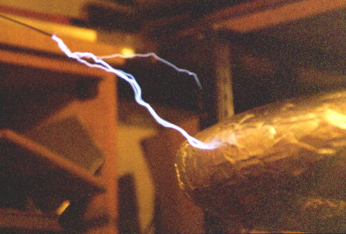
photo: the arc to a grounded wire 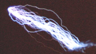
photo: the arc, close 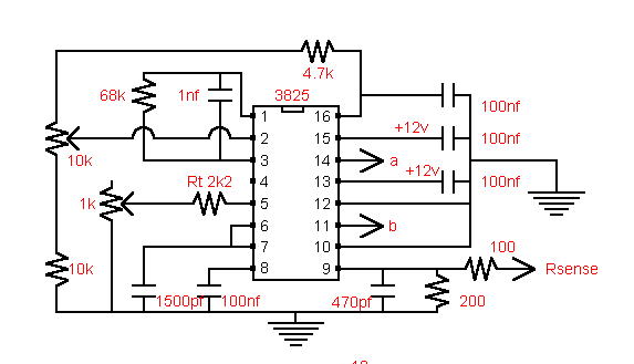
schematic: the UC3825 stage 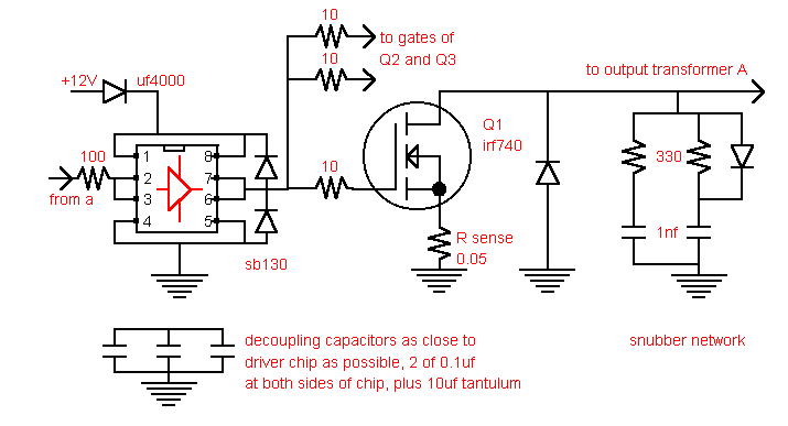
schematic: the FET stage, 4422 driver, IRF740, 0.05 ohm sense, snubber 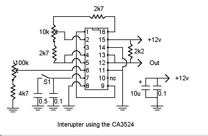
schematic: the CA3524 interrupter
Sources
- Internet Archive: Alan Sharp, An Experimental Solid State Lightning Coil (4 Oct 1999)
- Internet Archive: Alan Sharp's Home Page (6 Jun 2000)
This is the card from the driver tree, written from what the builder published. Send corrections through the forum.