The page as archived on 6 Dec 2002. In their words, the general idea is to take the sine wave off the resonator, square it at the zero crossing and feed it back into the power electronics, “nothing more than a large... a very large... oscillator.” A wire antenna (a clip cord will do), about 12 in long and 12 in from the coil, goes into a MAX913 comparator through a DC blocking capacitor, clamped by 1N34A diodes, against a 1 V reference. A 74LS14 Schmitt buffer adds hysteresis. MAX4420 and MAX4429 gate drivers feed a four-secondary gate transformer into a half or full bridge of IRF840, FQP13N50 or IRFP460. Their coil had a 4.5 by 16 in secondary of 28 AWG over a 15-turn 6.5 in primary of 12 AWG. It made a 5 in flaming brush at under 500 W from a full bridge of IRFP460s, and the scope shots show near-perfect zero-voltage switching. Ward's SSTC-1 of May 2003 is this circuit on a half bridge of IRFP260s, with a 555 to kick it into oscillation.
Schematics and photos
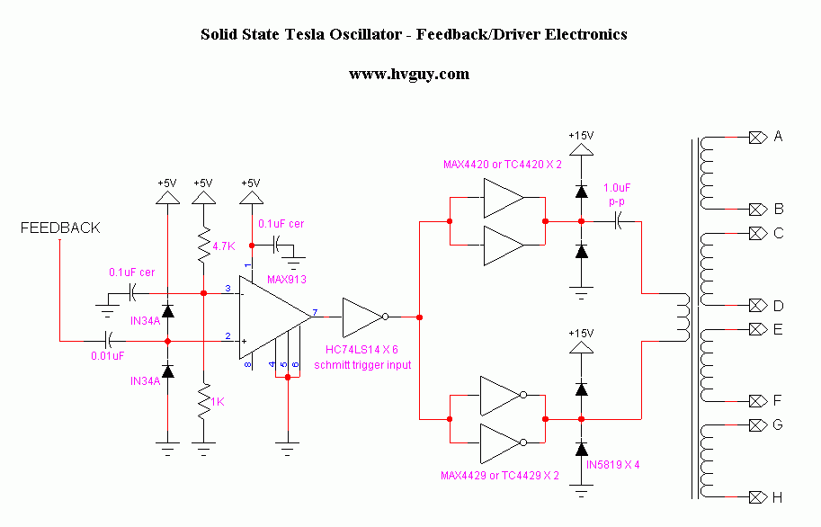
schematic: Solid State Tesla Oscillator, feedback and driver electronics, www.hvguy.com 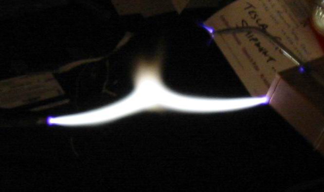
photo: the discharge to a grounded object 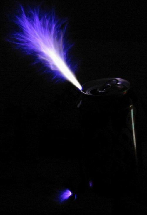
photo: the brush off the toroid 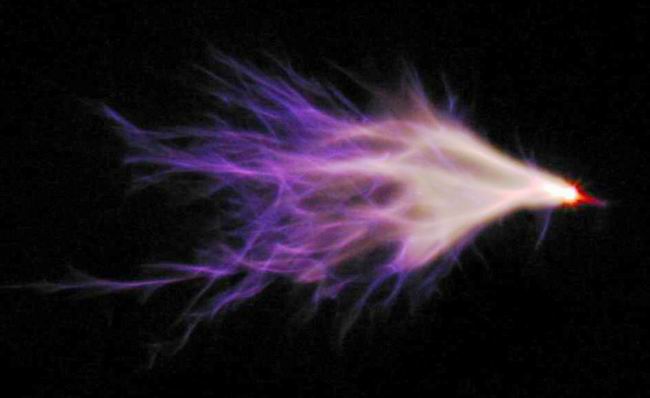
photo: the brush, second shot 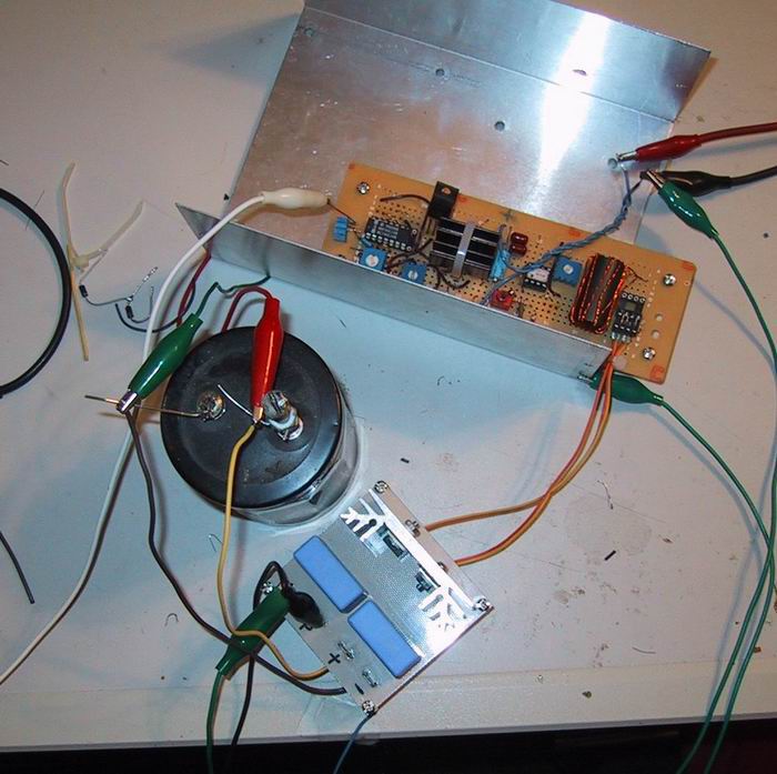
photo: the first bench setup 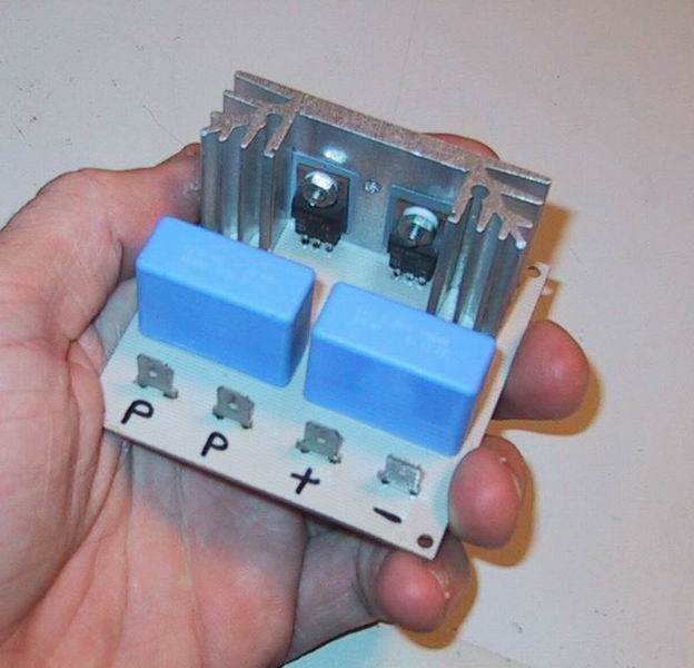
photo: the half bridge, in a hand 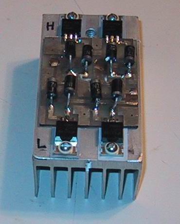
photo: the IRFP460 H bridge on its heatsink 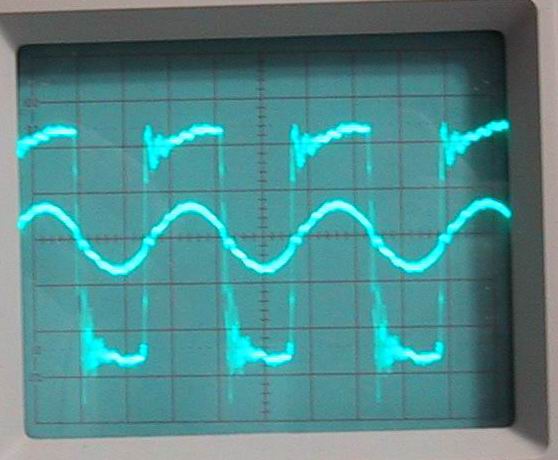
scope: zero-voltage switching, close in
Sources
This is the card from the driver tree, written from what the builder published. Send corrections through the forum.